traceRays
Description
Add-On Required: This feature requires the Optical Design and Simulation Library for Image Processing Toolbox add-on.
rb = traceRays(opsys,Name=Value)FieldPoints=fieldPoint(Angle=[15 0]) specifies to trace rays from
light source in the yz-plane at 15 degrees below the optical axis,
located at an infinite distance away from the first surface in the optical system.
Examples
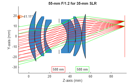
Load a double Gauss lens from a ZMX file into the workspace.
opsys = zmximport("DoubleGaussLens.zmx");Define a field point representation of two light sources using the fieldPoint function. The light sources are located at an infinite distance away from the first surface of the optical system, at 10 and 15 degrees below the optical axis in the *yz-*plane.
fp = fieldPoint(Angles=[10 0; 15 0]);
Trace rays through the optical system using the traceRays object function. Specify the ray wavelength as the Fraunhofer d line using the Wavelength name-value argument, and the sampling surface as the entrance pupil using the SamplingSurface name-value argument.
rb = traceRays(opsys,FieldPoints=fp,Wavelength=587.5618,SamplingSurface="entrance-pupil");Trace marginal rays through the optical system using the traceMarginalRays object function.
mr = traceMarginalRays(opsys,FieldPoints=fp,Wavelength=587.5618);
Display the optical system using the view2d object function, and visualize the traced rays through the system using the addRays object function. The marginal and sample rays are visualized in green and red, respectively.
hv = view2d(opsys);
addRays(hv,rb,Color="r")
addRays(hv,mr,Color="g")
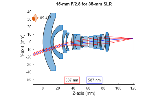
Load a wide angle lens from a ZMX file into the workspace.
opsys = zmximport("WideAngleLens.zmx");Define a field angle representation of a light source at infinity, with a field angle of 20 degrees from the z-axis, using the fieldPoint function.
fp = fieldPoint(Angles=[20 0]);
Trace a chief ray through the optical system using the traceChiefRay object function.
cr = traceChiefRay(opsys,FieldPoints=fp,Wavelengths=587);
Define a hexapolar sampling grid of coordinate points, through which to sample traced rays, using the samplingGrid function.
sg = samplingGrid("Hexapolar",6);Trace rays through the optical system using the traceRays object function. Specify the defined hexapolar sampling grid using the SamplingGrid name-value argument.
rb = traceRays(opsys,FieldPoints=fp,Wavelength=587,SamplingGrid=sg);
Display the optical system using the view2d object function, and visualize the traced rays through the system using the addRays object function. The chief and sample rays are visualized in blue and red, respectively.
hv = view2d(opsys);
addRays(hv,rb,Color="r")
addRays(hv,cr,Color="b")
Input Arguments
Name-Value Arguments
Output Arguments
Version History
Introduced in R2026a