Main Content

lidarSensor

Simulate lidar sensor readings

Since R2022a

Description

The lidarSensor System object™ simulates a lidar sensor mounted on an ego vehicle and outputs point cloud data for a given scene. The generated data is with respect to the ego vehicle coordinate system based on the sensor pose and the actors present in the scene. You can use the drivingScenario (Automated Driving Toolbox) object to create a scenario containing actors and trajectories, then generate the point cloud data for the scenario by using the lidarSensor object.

You can also use the lidarSensor object with vehicle actors in RoadRunner Scenario simulation. First you must create a SensorSimulation (Automated Driving Toolbox) object to interface sensors with RoadRunner Scenario and then register the lidar as a sensor model using the addSensors (Automated Driving Toolbox) object function before simulation. For more information, see Add Lidar Sensor Model with Simulated Weather Effects to RoadRunner Scenario. (since R2024a)

To simulate lidar sensor using this object:

  1. Create the lidarSensor object and set its properties.

  2. Call the object with arguments, as if it were a function.

To learn more about how System objects work, see What Are System Objects?

Creation

Description

lidar = lidarSensor creates a lidarSensor object with default property values. You can use this object to generate lidar point cloud data for a given 3-D environment.

example

lidar = lidarSensor(Name=Value) sets the properties of the object using one or more name-value arguments. For example, lidarSensor(UpdateRate=0.2) creates a lidarSensor object that generates point cloud detections at every 0.2 seconds.

Properties

expand all

Unless otherwise indicated, properties are nontunable, which means you cannot change their values after calling the object. Objects lock when you call them, and the release function unlocks them.

If a property is tunable, you can change its value at any time.

For more information on changing property values, see System Design in MATLAB Using System Objects.

Unique identifier for the sensor, specified as a positive integer. In a multisensor system, this index distinguishes different sensors from one another.

Data Types: single | double | int8 | int16 | int32 | int64 | uint8 | uint16 | uint32 | uint64

ActorID of the ego vehicle, specified as a positive integer. The ego vehicle is the actor on which the sensor is mounted, and ActorID is the unique identifier for an actor.

Data Types: single | double | int8 | int16 | int32 | int64 | uint8 | uint16 | uint32 | uint64

Time interval between two consecutive sensor updates, specified as a positive scalar. The lidarSensor object generates new detections at the interval specified by this property. The value must be an integer multiple of the simulation time. Updates requested from the sensor in between the update intervals contain no detections. Units are in seconds.

Data Types: single | double

Sensor center position, specified as a three-element vector of the form [x y height]. The values of x and y represent the location of the sensor with respect to the x- and y-axes of the ego vehicle coordinate system. height is the height of the sensor above the ground. The default value defines a lidar sensor mounted on the front edge of the roof of a sedan. Units are in meters.

Data Types: single | double

Sensor orientation, specified as a three-element vector of the form, [roll pitch yaw]. These values are with respect to the ego vehicle coordinate system. Units are in degrees.

  • roll — The roll angle is the angle of rotation around the front-to-back axis, which is the x-axis of the ego vehicle coordinate system. A positive roll angle corresponds to a clockwise rotation when looking in the positive direction of the x-axis.

  • pitch — The pitch angle is the angle of rotation around the side-to-side axis, which is the y-axis of the ego vehicle coordinate system. A positive roll angle corresponds to a clockwise rotation when looking in the positive direction of the y-axis.

  • yaw — The yaw angle is the angle of rotation around the vertical axis,which is the z-axis of the ego vehicle coordinate system. A positive roll angle corresponds to a clockwise rotation when looking in the positive direction of the z-axis. This rotation appears counter-clockwise when viewing the vehicle from above.

Data Types: single | double

Maximum detection range of the lidar sensor, specified as a positive scalar in meters. The sensor cannot detect roads and actors beyond this range.

Data Types: single | double | int8 | int16 | int32 | int64 | uint8 | uint16 | uint32 | uint64

Accuracy of the sensor range measurement, specified as a positive scalar. Units are in meters.

Data Types: single | double

Point cloud data has added noise, specified as true or false. When set to true, the function adds random Gaussian noise to each point in the point cloud using the RangeAccuracy property as one standard deviation. Otherwise, the data has no noise.

Note

When you specify the FogVisibilty and Rainrate properties while HasNoise value is set to true, the function adds noise points with high intensity values. The ActorID and the ClassID of these noise points in 0 in the clusters output.

Data Types: logical

Output point cloud is organized, specified as true or false.

  • true — The function returns an organized point cloud of the form M-by-N-by-3, where M is the number of elevation channels and N is the number of azimuth channels in the point cloud.

  • false — The function returns an unorganized point cloud of the form P-by-3, where P is the number of points in the point cloud.

Data Types: logical

Azimuth resolution of the lidar sensor, specified as a positive scalar in degrees.

Data Types: single | double

Elevation resolution of the lidar sensor, specified as a positive scalar in degrees.

Note

The System object ignores this property when you specify the ElevationAngles property.

Data Types: single | double

Azimuth limits of the lidar sensor, specified as a two-element vector of the form [min max]. The values must be in the range [-180, 180], max must be greater than min. Units are in degrees.

Data Types: single | double

Elevation limits of the lidar sensor, specified as a two-element vector of the form [min max]. The values must be in the range [-180, 180], max must be greater than min. Units are in degrees.

Note

The System object ignores this property when you specify the ElevationAngles property.

Data Types: single | double

Elevation angles of the lidar sensor, specified as an N-element vector. N is the number of elevation channels. The elements of the vector must be in the increasing order and their values must be in the range [-180, 180]. Units are in degrees.

Note

When you specify this property, the System object ignores the ElevationResolution and ElevationLimits properties.

Data Types: single | double

Physical characteristics of the actors in the scene, specified as a structure or as an L-element array of structures. L is the number of actors in the scene.

To generate an array of actor profile structures for your driving scenario, use the actorProfiles (Automated Driving Toolbox) function. You can also create these structures manually. This table shows the valid structure fields.

FieldDescriptionValue
ActorIDUnique identifier for the actor. In a scene with multiple actors, this value distinguishes different actors from one another.Positive integer
ClassID

User-defined classification ID for the actor.

ClassIDClass Name
1Car
2Truck
3Bicycle
4Pedestrian
5Jersey Barrier
6Guardrail

Positive scalar
LengthLength of the actor in meters.Positive scalar
WidthWidth of the actor in meters.Positive scalar
HeightHeight of the actor in meters.Positive scalar
OriginOffset

Offset of the rotational center of the actor from its geometric center. The rotational center, or origin, is located at the bottom center of the actor. For vehicles, the rotational center is the point on the ground beneath the center of the rear axle.

A three-element vector of the form [x y z]. Units are in meters.

MeshVerticesVertices of the actor in mesh representation.N-by-3 numeric matrix, where each row defines a vertex in 3-D space.
MeshFacesFace of the actor in mesh representation.M-by-3 integer matrix, where each row represents a triangle defined by vertex IDs, which are the row numbers of MeshVertices.
MeshTargetReflectancesMaterial reflectance for each triangular face of the actor.M-by-1 numeric vector, where M is the number of triangle faces of the actor. Each value must be in the range [0, 1].

For more information about these structure fields, see the actor (Automated Driving Toolbox) and vehicle (Automated Driving Toolbox) functions.

Visible distance in fog, specified as a positive scalar, in meters. This value must not be greater than 1000. A higher value indicates a better visibility and a lower fog impact. The default value of 1000 indicates clear visibility, or no fog.

Note

When you specify both the FogVisibility and Rainrate properties, the function simulates only the foggy weather.

Data Types: single | double

Rate of rainfall, specified as a positive scalar in millimeters per hour. This value must be less than or equal to 200. Increasing this value increases the impact of the rain on the generated point cloud. The default value is 0, indicating no rainfall.

Note

When you specify both the FogVisibility and Rainrate properties, the function simulates only the foggy weather.

Data Types: single | double

Since R2024a

Name of the sensor model, specified as a character vector or string scalar. For information on the valid sensor model names, see Supported Sensors.

This property sets default elevation angle values based on the specified sensor. To apply custom elevation angles, use the ElevationAngles property.

Data Types: char | string

Since R2024a

Motion distortion flag, specified as a logical 1 (true) or 0 (false).

  • true or logical 1 — Simulate motion distortion.

  • false or logical 0 — Do not simulate motion distortion.

Data Types: logical

Since R2024a

Firing times of the lasers in the lidar sensor, specified as a duration object or N-element array of duration objects. N is the number of elevation angles. Use a single duration object to specify the same firing time for all lasers. Units are in seconds.

You can specify elevation angles by using the ElevationAngles property. If you do not specify the ElevationAngles property, the System object determines the elevation angles by using the ElevationLimits and ElevationResolution properties.

Data Types: duration

Usage

Description

ptCloud = lidar(time) generates a lidar point cloud, ptCloud, at the specified simulation time time. The function generates data at time intervals specified by the UpdateRate property of the lidarSensor object lidar.

Note

Use this syntax to generate point cloud data for a drivingScenario (Automated Driving Toolbox) object after adding the lidarSensor object to the scenario using the addSensors (Automated Driving Toolbox) function. This also updates the ActorProfiles property of the lidarSensor object based on the values of the connected scenario.

ptCloud = lidar(tgtPoses,time) generates a lidar point cloud, ptCloud, using the actor poses tgtPoses at the specified simulation time time.

[ptCloud,isValidTime,clusters] = lidar(tgtPoses,time) additionally returns isValidTime, which indicates whether the simulation time is valid, and clusters, which contain the classification data of the output point cloud.

Input Arguments

expand all

Actor poses in the scene, specified as an L- element array of structures. Each structure corresponds to an actor. L is the number of actors used.

You can generate this structure using the actorPoses (Automated Driving Toolbox) function. You can also create these structures manually. Each structure has these fields:

FieldDescriptionValue
ActorIDUnique identifier for the actor.Positive scalar
PositionPosition of the actor with respect to the ego vehicle coordinate system, in meters.Vector of the form [x y z]
VelocityVelocity (V) of the actor, in meters per second, along the x-, y-, and z- directions.

A vector of the form [Vx Vy Vz]

Default: [0 0 0]

RollRoll angle of the actor in degrees.

Numeric scalar

Default: 0

PitchPitch angle of the actor in degrees.

Numeric scalar

Default: 0

YawYaw angle of the actor in degrees.

Numeric scalar

Default: 0

AngularVelocityAngular velocity (ω) of the actor, in degrees per second, along the x-, y-, and z- directions.

Vector of the form [ωx ωy ωz]

Default: [0 0 0]

Simulation time, specified as a positive scalar. The lidarSensor object generates new detections at the interval specified by the UpdateRate property. The value of the UpdateRate property must be an integer multiple of the simulation time interval. Updates requested from the sensor between update intervals do not generate a point cloud.

Data Types: single | double

Output Arguments

expand all

Point cloud data generated from the scene, returned as a pointCloud object.

Valid simulation time, returned as a logical 0(false) or 1(true). The value is 0 for updates requested at times between the update interval specified by the UpdateRate property.

Classification data of actors in the scene, returned as an M-by-N-by-2 array for an organized point cloud or a P-by-2 matrix for an unorganized point cloud. The first column contains the ActorIDs and the second column contains the ClassIDs of the target actors. M, N are the number of rows and columns in the organized point cloud, and P is the number of points in the unorganized point cloud.

Object Functions

To use an object function, specify the System object as the first input argument. For example, to release system resources of a System object named obj, use this syntax:

release(obj)

expand all

stepRun System object algorithm
releaseRelease resources and allow changes to System object property values and input characteristics
resetReset internal states of System object

Examples

collapse all

Load synthetic scene data containing actor profiles and target poses generated using the drivingScenario (Automated Driving Toolbox) object into the workspace.

sceneData = load("scene_data.mat");
sceneActorProfiles = sceneData.ActorProfiles;
sceneTargetPoses = sceneData.TargetPoses;

Load the target material reflectance data.

reflectanceData = load("scene_target_reflectances.mat");
targetReflectance = reflectanceData.TargetReflectances;

Define the reflectances for each actor.

for i = 1:numel(sceneActorProfiles)
    sceneActorProfiles(i).MeshTargetReflectances = targetReflectance{i};
end

Create a lidarSensor System object, and define the actor profiles for the object.

lidarS = lidarSensor(AzimuthResolution=0.5,RainRate=2.5);
lidarS.ActorProfiles = sceneActorProfiles;

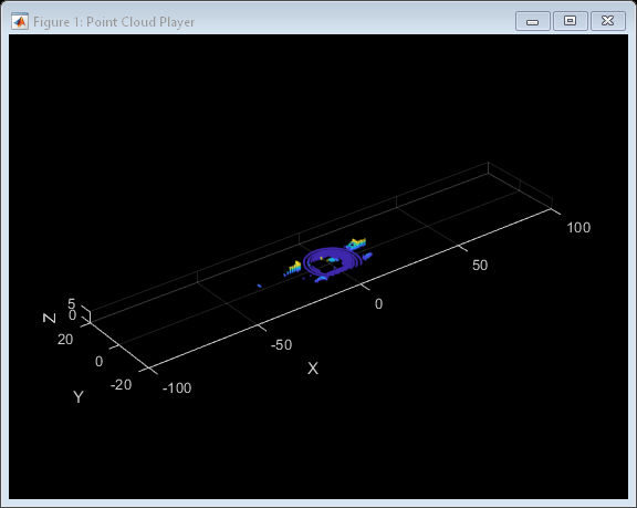
Create a pcplayer object to visualize the lidar sensor point cloud detections.

player = pcplayer([-100 100],[-20 20],[0 5]);

Generate and visualize the point cloud detections at valid simulation times.

  for i = 1:5:numel(sceneTargetPoses)
     if(~player.isOpen)
         break
     end
     [ptCloud,isValid] = lidarS(sceneTargetPoses{i},i*0.1);
     if(isValid)
         view(player,ptCloud)
     end
  end

Version History

Introduced in R2022a

expand all

See Also

Apps

Functions

Blocks