phased.HeterogeneousURA
Heterogeneous uniform rectangular array
Description
The HeterogeneousURA object constructs a heterogeneous
uniform rectangular array (URA).
To compute the response for each element in the array for specified directions:
Define and set up your uniform rectangular array. See Construction.
Call
stepto compute the response according to the properties ofphased.HeterogeneousURA. The behavior ofstepis specific to each object in the toolbox.
Note
Starting in R2016b, instead of using the step method
to perform the operation defined by the System object™, you can
call the object with arguments, as if it were a function. For example, y
= step(obj,x) and y = obj(x) perform
equivalent operations.
Construction
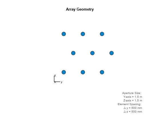
H = phased.HeterogeneousURA creates a heterogeneous
uniform rectangular array (URA) System object, H.
This object models a heterogeneous URA formed with sensor elements
whose pattern may vary from element to element. Array elements are
distributed in the yz-plane
in a rectangular lattice. An M-by-N heterogeneous
URA has M rows and N columns.
The array boresight direction is along the positive x-axis.
The default array is a 2-by-2 URA of isotropic antenna elements.
H = phased.HeterogeneousURA( creates
the object, Name,Value)H, with each specified property Name
set to the specified Value. You can specify additional name-value
pair arguments in any order as (Name1,Value1,...,NameN,ValueN).
Properties
| Set of elements used in the array Set of elements used in the sensor array, specified as a row MATLAB cell array.
Elements specified in the Default: One cell containing one isotropic antenna element |
| Elements location assignment This property specifies the mapping of elements in the array.
The property assigns elements to their locations in the array using
the indices into the Default: |
| Element spacing A 1-by-2 vector or a scalar containing the element spacing (in
meters) of the array. If Default: |
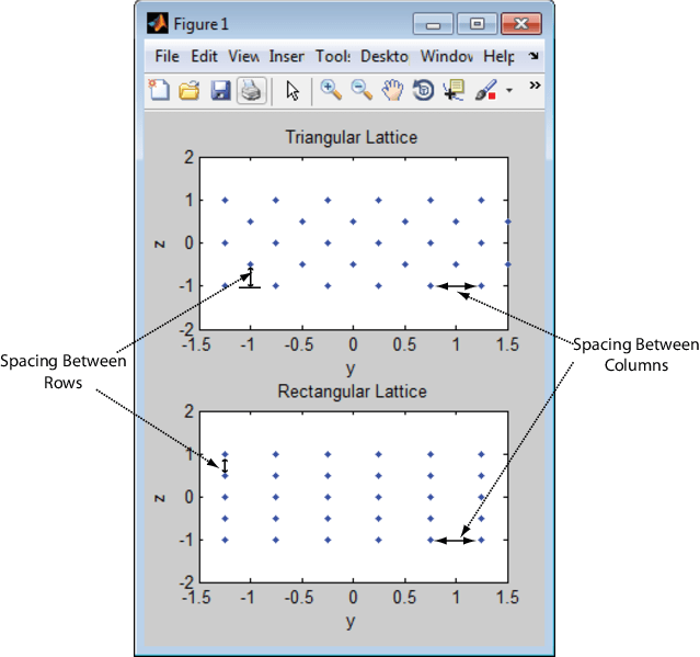
| Element lattice Specify the element lattice as one of Default: |
| Default: |
| Element tapers Element tapers, specified as a complex-valued scalar, or a complex-valued
1-by-MN row vector, MN-by-1
column vector, or M-by-N matrix.
Tapers are applied to each element in the sensor array. Tapers are
often referred to as element weights. M is
the number of elements along the z-axis, and N is
the number of elements along y-axis. M and N correspond
to the values of Default: 1 |
Methods
Specific to
phased.HeterogeneousURA Object | |
|---|---|
beamwidth | Compute and display beamwidth of an array |
collectPlaneWave | Simulate received plane waves |
directivity | Directivity of heterogeneous uniform rectangular array |
getElementNormal | Normal vector to array elements |
getElementPosition | Positions of array elements |
getNumElements | Number of elements in array |
getTaper | Array element tapers |
isPolarizationCapable | Polarization capability |
pattern | Plot heterogeneous URA directivity and power pattern |
patternAzimuth | Plot heterogeneous URA directivity or pattern versus azimuth |
patternElevation | Plot heterogeneous URA array directivity or pattern versus elevation |
perturbations | Perturbations defined on phased array |
perturbedArray | Apply perturbations to phased array |
perturbedPattern | Compute and plot azimuth pattern of perturbed array |
sidelobelevel | Peak and integrated sidelobe levels |
step | Output responses of array elements |
viewArray | View array geometry |
| Common to All System Objects | |
|---|---|
release | Allow System object property value changes |
Examples
More About
References
[1] Brookner, E., ed. Radar Technology. Lexington, MA: LexBook, 1996.
[2] Brookner, E., ed. Practical Phased Array Antenna Systems. Boston: Artech House, 1991.
[3] Mailloux, R. J. “Phased Array Theory and Technology,” Proceedings of the IEEE, Vol., 70, Number 3, 1982, pp. 246–291.
[4] Mott, H. Antennas for Radar and Communications, A Polarimetric Approach. New York: John Wiley & Sons, 1992.
[5] Van Trees, H. Optimum Array Processing. New York: Wiley-Interscience, 2002.
Extended Capabilities
Version History
Introduced in R2013a


