show
Show robot model in figure
Description
show( uses
the joint positions specified in robot,configuration)configuration to
show the robot body frames.
show(___, specifies options
using one or more name-value pair arguments in addition to any combination of input
arguments from previous syntaxes. For example, Name=Value)Frames="off" hides
the rigid body frames in the figure.
ax = show(___)
Examples
Load a robot and get its home configuration.
robot = loadrobot("abbIrb120",DataFormat="row");
c = homeConfiguration(robot);
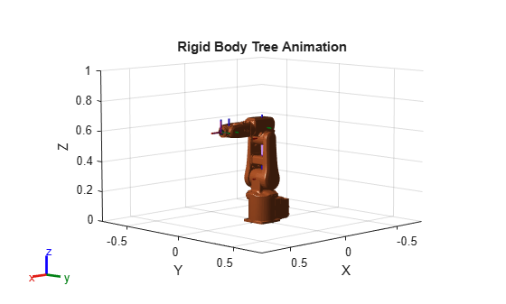
Create configuration waypoint trajectory that rotates the base of the rigid body tree 360 degrees.
numSamples = 100;
cWpts = zeros(numSamples,size(c,2));
cWpts(:,1) = linspace(0,2*pi,numSamples);
Show the plot the robot in the first configuration. DisplayBodyDetails must be off to enable the animation.
ax = show(robot,cWpts(1,:),FastUpdate=true,PreservePlot=false,DisplayBodyDetails="off");
title("Rigid Body Tree Animation")
axis([-0.75 0.75 -0.75 0.75 0 1])
hold on
Plot every configuration making sure you use the drawnow function to create animation time control bar under the figure to playback the animation.
rc = rateControl(60); % 60 Hz
for i = 1:numSamples
show(robot,cWpts(i,:),Parent=ax,FastUpdate=true,PreservePlot=false,DisplayBodyDetails="off");
    drawnow
    waitfor(rc);
end
hold off
You can import robots that have .stl files associated with the Unified Robot Description format (URDF) file to describe the visual geometries of the robot. Each rigid body has an individual visual geometry specified. The importrobot function parses the URDF file to get the robot model and visual geometries. The function assumes that visual geometry and collision geometry of the robot are the same and assigns the visual geometries as collision geometries of corresponding bodies.
Use the show function to display the visual and collision geometries of the robot model in a figure. You can then interact with the model by clicking components to inspect them and right-clicking to toggle visibility.
Import a robot model as a URDF file. The .stl file locations must be properly specified in this URDF. To add other .stl files to individual rigid bodies, see addVisual.
robot = importrobot('iiwa14.urdf');Visualize the robot with the associated visual model. Click bodies or frames to inspect them. Right-click bodies to toggle visibility for each visual geometry.
show(robot,Visuals="on",Collisions="off");

Visualize the robot with the associated collision geometries. Click bodies or frames to inspect them. Right-click bodies to toggle visibility for each collision geometry.
show(robot,Visuals="off",Collisions="on");

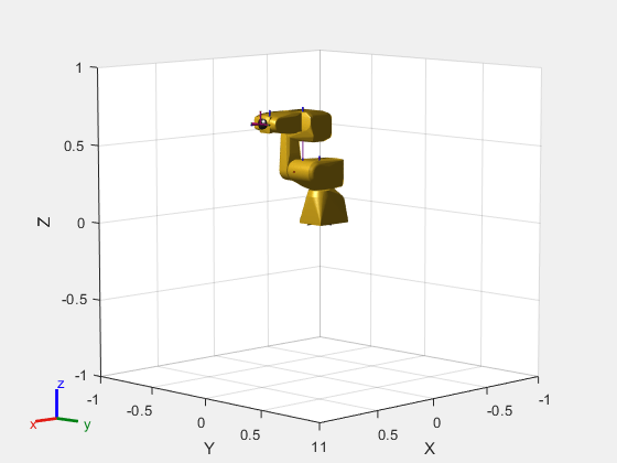
Show different configurations of a robot created using a rigidBodyTree model. Use the homeConfiguration or randomConfiguration functions to generate the structure that defines all the joint positions.
Load a FANUC LR Mate 200ib from the Robotics System Toolbox™ loadrobot. It is returned as a rigidBodyTree object.
robot = loadrobot("fanucLRMate200ib");
showdetails(robot)
-------------------- Robot: (9 bodies) Idx Body Name Joint Name Joint Type Parent Name(Idx) Children Name(s) --- --------- ---------- ---------- ---------------- ---------------- 1 base base_link-base fixed base_link(0) 2 link_1 joint_1 revolute base_link(0) link_2(3) 3 link_2 joint_2 revolute link_1(2) link_3(4) 4 link_3 joint_3 revolute link_2(3) link_4(5) 5 link_4 joint_4 revolute link_3(4) link_5(6) 6 link_5 joint_5 revolute link_4(5) link_6(7) 7 link_6 joint_6 revolute link_5(6) flange(8) tool0(9) 8 flange joint_6-flange fixed link_6(7) 9 tool0 link_6-tool0 fixed link_6(7) --------------------
Create a structure for the home configuration of the robot. The structure has joint names and positions for each body on the robot model.
config = homeConfiguration(robot)
config=1×6 struct array with fields:
    JointName
    JointPosition
Show the home configuration using show. You do not need to specify a configuration input.
show(robot);
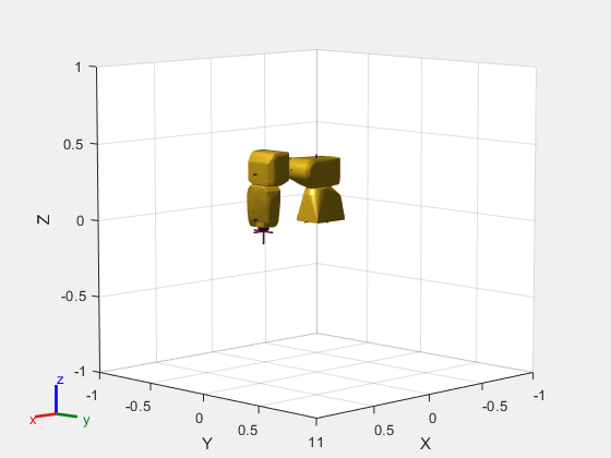
Modify the configuration and set the second joint position to pi/2. Show the resulting change in the robot configuration.
config(2).JointPosition = pi/2;
show(robot,config);
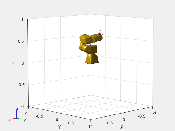
Create random configurations and show them.
show(robot,randomConfiguration(robot));
Use the Denavit-Hartenberg (DH) parameters of the Puma560® robot to build a robot. Each rigid body is added one at a time, with the child-to-parent transform specified by the joint object.
The DH parameters define the geometry of the robot with relation to how each rigid body is attached to its parent. For convenience, setup the parameters for the Puma560 robot in a matrix [1]. The Puma robot is a serial chain manipulator. The DH parameters are relative to the previous row in the matrix, corresponding to the previous joint attachment.
dhparams = [0   	pi/2	0   	0;
            0.4318	0       0       0
            0.0203	-pi/2	0.15005	0;
            0   	pi/2	0.4318	0;
            0       -pi/2	0   	0;
            0       0       0       0];
Create a rigid body tree object to build the robot.
robot = rigidBodyTree;
Create the first rigid body and add it to the robot. To add a rigid body:
Create a
rigidBodyobject and give it a unique name.Create a
rigidBodyJointobject and give it a unique name.Use
setFixedTransformto specify the body-to-body transformation using DH parameters. The last element of the DH parameters,theta, is ignored because the angle is dependent on the joint position.Call
addBodyto attach the first body joint to the base frame of the robot.
body1 = rigidBody('body1');
jnt1 = rigidBodyJoint('jnt1','revolute');

setFixedTransform(jnt1,dhparams(1,:),'dh');
body1.Joint = jnt1;

addBody(robot,body1,'base')
Create and add other rigid bodies to the robot. Specify the previous body name when calling addBody to attach it. Each fixed transform is relative to the previous joint coordinate frame.
body2 = rigidBody('body2');
jnt2 = rigidBodyJoint('jnt2','revolute');
body3 = rigidBody('body3');
jnt3 = rigidBodyJoint('jnt3','revolute');
body4 = rigidBody('body4');
jnt4 = rigidBodyJoint('jnt4','revolute');
body5 = rigidBody('body5');
jnt5 = rigidBodyJoint('jnt5','revolute');
body6 = rigidBody('body6');
jnt6 = rigidBodyJoint('jnt6','revolute');

setFixedTransform(jnt2,dhparams(2,:),'dh');
setFixedTransform(jnt3,dhparams(3,:),'dh');
setFixedTransform(jnt4,dhparams(4,:),'dh');
setFixedTransform(jnt5,dhparams(5,:),'dh');
setFixedTransform(jnt6,dhparams(6,:),'dh');

body2.Joint = jnt2;
body3.Joint = jnt3;
body4.Joint = jnt4;
body5.Joint = jnt5;
body6.Joint = jnt6;

addBody(robot,body2,'body1')
addBody(robot,body3,'body2')
addBody(robot,body4,'body3')
addBody(robot,body5,'body4')
addBody(robot,body6,'body5')
Verify that your robot was built properly by using the showdetails or show function. showdetails lists all the bodies in the MATLAB® command window. show displays the robot with a given configuration (home by default). Calls to axis modify the axis limits and hide the axis labels.
showdetails(robot)
--------------------
Robot: (6 bodies)

 Idx    Body Name   Joint Name   Joint Type    Parent Name(Idx)   Children Name(s)
 ---    ---------   ----------   ----------    ----------------   ----------------
   1        body1         jnt1     revolute             base(0)   body2(2)
   2        body2         jnt2     revolute            body1(1)   body3(3)
   3        body3         jnt3     revolute            body2(2)   body4(4)
   4        body4         jnt4     revolute            body3(3)   body5(5)
   5        body5         jnt5     revolute            body4(4)   body6(6)
   6        body6         jnt6     revolute            body5(5)
--------------------
show(robot);
axis([-0.5,0.5,-0.5,0.5,-0.5,0.5])
axis off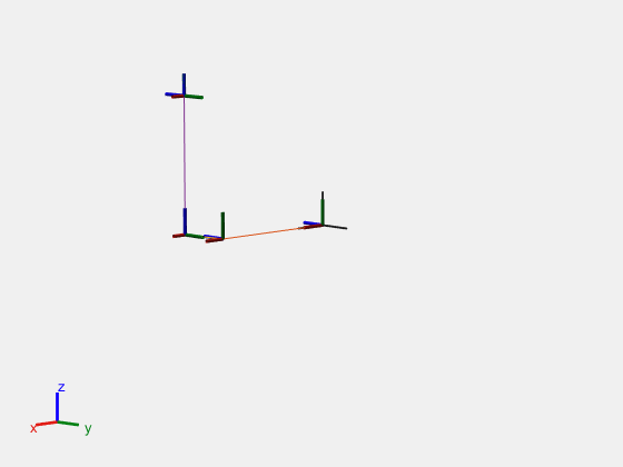
[1] Corke, P. I., and B. Armstrong-Helouvry. “A Search for Consensus among Model Parameters Reported for the PUMA 560 Robot.” Proceedings of the 1994 IEEE International Conference on Robotics and Automation, IEEE Computer. Soc. Press, 1994, pp. 1608–13. DOI.org (Crossref), doi:10.1109/ROBOT.1994.351360.
Load a robot model and modify the collision meshes. Clear existing collision meshes, add simple collision object primitives, and check whether certain configurations are in collision.
Load Robot Model
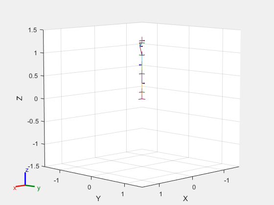
Load a preconfigured robot model into the workspace using the loadrobot function. This model already has collision meshes specified for each body. Iterate through all the rigid body elements and clear the existing collision meshes. Confirm that the existing meshes are gone.
robot = loadrobot("kukaIiwa7",DataFormat="column");

for i = 1:robot.NumBodies
    clearCollision(robot.Bodies{i})
end

show(robot,Collisions="on",Visuals="off");
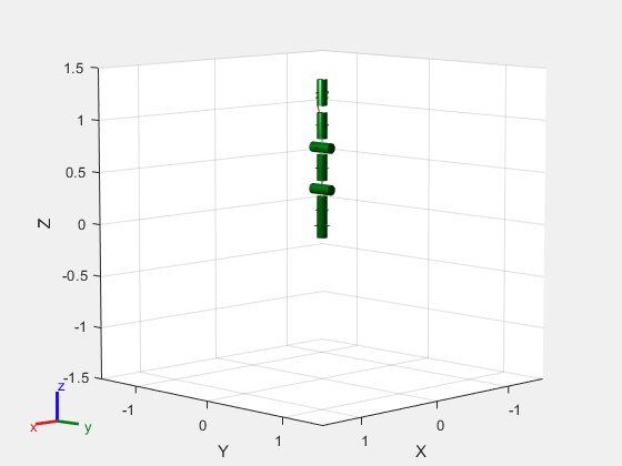
Add Collision Cylinders
Iteratively add a blue collision cylinder to each body and set the transparency to opaque. Skip some bodies for this specific model, as they overlap and always collide with the end effector (body 10).
collisionObj = collisionCylinder(0.05,0.25);

for i = 1:robot.NumBodies
    if i > 6 && i < 10
        % Skip these bodies.
    else
        addCollision(robot.Bodies{i}, collisionObj, FaceColor=[0 0 1], FaceAlpha=1)
    end
end

show(robot,Collisions="on",Visuals="off");
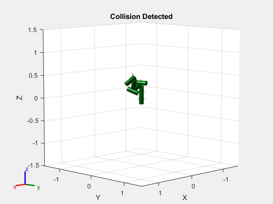
Check for Collisions
Generate a series of random configurations. Check whether the robot is in collision at each configuration. Visualize each configuration that has a collision.
figure
rng(0) % Set random seed for repeatability.
for i = 1:20
    config = randomConfiguration(robot);
    isColliding = checkCollision(robot,config,SkippedSelfCollisions="parent");
    if isColliding
        show(robot,config,Collisions="on",Visuals="off");
        title("Collision Detected")
    else
        % Skip non-collisions.
    end
end
Input Arguments
Name-Value Arguments
Specify optional pairs of arguments as
Name1=Value1,...,NameN=ValueN, where Name is
the argument name and Value is the corresponding value.
Name-value arguments must appear after other arguments, but the order of the
pairs does not matter.
Example: Frames="off" hides the rigid body frames in the
figure.
Parent of axes, specified as an Axes object in which to
draw the robot. By default, the robot is plotted in the active
axes.
Option to preserve robot plot, specified as a logical
1 (true) or
0 (false). When you specify
PreservePlot as true, you
must also use hold
on so that show does not
overwrite previous rigid body tree patches in the axes that were
displayed by calling show. When you specify
PreservePlot as false, the
show overwrites previous plots of the
rigid body tree in the same axes regardless of the current
hold value.
Note
If PreservePlot is true,
then the FastUpdate argument must be
false.
Data Types: logical
Display body frames, specified as either "all",
"root" or "off".
"all"— Show both root and nonroot coordinate frames of rigid bodies in the rigid body tree.Note
When
FastUpdatename-value argument istrueandPreservePlotname-value argument isfalse, theshowfunction does not plot the nonroot frames."root"— Show only the root frames of the rigid body tree. The root frame of a rigid body is the coordinate frame located at the origin of that body."off"— Do not show any frames.
Data Types: char | string
Size of the body frames, specified as a positive numeric scalar.
Display visual geometries, specified as either "on"
or "off". Individual visual geometries can also be
turned off by right-clicking them in the figure.
Specify individual visual geometries using addVisual. To import a URDF robot model with
.stl files for meshes, see the importrobot
function.
Data Types: char | string
Display collision geometries, specified as the comma-separated pair
consisting of "Collisions" and
"on" or "off".
Add collision geometries to the individual rigid bodies in the robot
model using the addCollision function. To import a URDF robot model with
.stl files for meshes, see the importrobot
function.
Data Types: char | string
Position of the robot, specified as the comma-separated pair
consisting of "Position" and a four-element vector of
the form [x
y
z
yaw]. The x, y,
and z elements specify the position in meters, and
yaw specifies the yaw angle in radians.
Data Types: single | double
Fast updates to existing plot, specified as a logical
0
(false) or 1
(true). You must use the show
object function to initially display the robot model before you can
specify it with this argument.
Note
If FastUpdate is true, then
the PreservePlot argument must be
false.
Data Types: logical
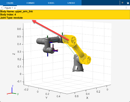
Display details of a rigid body on a mouse click, specified as
"on" or "off".
To interactively inspect bodies of the plotted rigid body tree, set
DisplayBodyDetails to "on".
This enables you to click on a rigid body to display information about
the rigid body in a yellow body details banner at the top of the figure.
The body details banner contains the body name, body index, and joint
type of the selected body. See the Tips
section for more information.
To enable rigid body tree animations in live code scripts, you must
set DisplayBodyDetails to "off".
See the Create Rigid Body Tree Animation
example for more information.
Output Arguments
Tips
Your robot model has visual components associated with it. Each rigidBody object contains a coordinate frame that is displayed as the body
frame. Each body also can have visual meshes associated with them. By default, both of
these components are displayed automatically. When the
DisplayBodyDetails name-value argument is
"on", you can inspect or modify the visual components of the
rigid body tree display. Click body frames or visual meshes to highlight them in yellow
and see the associated body name, index, and joint type in the yellow body details
banner. Right-click to toggle visibility of individual components.
Body Frames: Individual body frames are displayed as a 3-axis coordinate frame. Fixed frames are pink frames. Movable joint types are displayed as RGB axes. You can click a body frame to see the axis of motion. Prismatic joints show a yellow arrow in the direction of the axis of motion and, revolute joints show a circular arrow around the rotation axis.

Visual Meshes: Individual visual geometries are specified using
addVisualor by using theimportrobotto import a robot model with either a specified.stlor.daefile. By right-clicking individual bodies in a figure, you can turn off their meshes or specify theVisualsname-value pair to hide all visual geometries.