Extract Scene From Lidar Data
This example shows how to segment a scene from a Lidar data. The Lidar data set contains points that belong to the scene as well as the robot on which the Lidar sensors are mounted.
The example details the workflow used by the Create Environment Occupancy Map section of the Plan Collision-Free Path for Excavator Arm in MATLAB With Lidar Data example. To incorporate this workflow with motion planning of the excavator arm, see the Simulate Earth Moving with Autonomous Excavator in Construction Site example.
This example uses the following toolboxes:
Robotics System Toolbox™ — Model an excavator using
rigidBodyTree.Image Processing Toolbox™ and Computer Vision Toolbox™ — Visualize a point cloud using
pcshow(Computer Vision Toolbox) and merge multiple point clouds usingpcmerge(Computer Vision Toolbox).
Initial Setup
Import Robot Model
This example uses a model of an excavator in a construction scene.
Load the rigidBodyTree model of the excavator from the MAT file included with this example.
load MathScavator9000.matIn the Lidar data set, positive x-axis points in the forward direction of the excavator. In the rigidBodyTree model, the positive y-axis points in the forward direction of the excavator. Rotate the rigidBodyTree model by -90 degrees around the z-axis so that the orientation of the rigidBodyTree model matches the orientation specified in the Lidar data set. The helper function exampleHelperSetRigidBodyTreeRotation adds a rotating body with a fixed joint that offsets the base of the excavator from the world frame by -90 degrees along the z-axis.
tform = eul2tform([-pi/2,0,0]);
excavatorRBT = exampleHelperSetRigidBodyTreeRotation(excavatorRBT, tform);
excavatorRBT.DataFormat = "row";
show(excavatorRBT);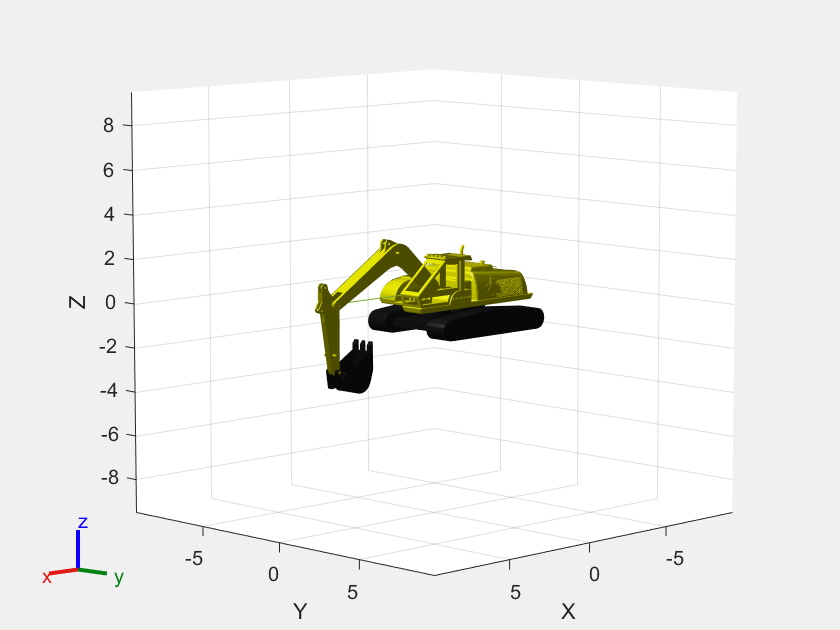
Import Lidar Data
You can obtain Lidar data from sensors in a Simulation 3D scene. For this example, you import the Lidar data is imported from a MAT file.
load exampleLidarPointClouds.mat
exampleLidarPointClouds = exampleHelperLidarData(lidarData);
load lidarSensorParameters.mat
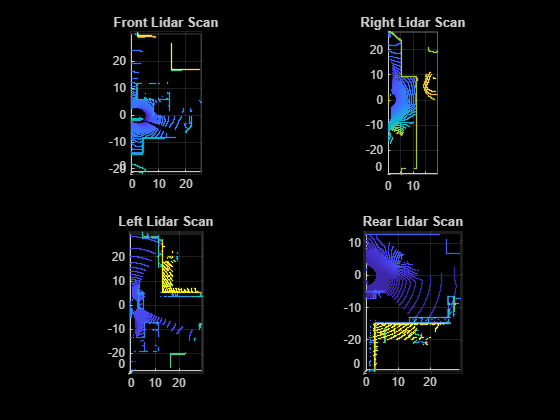
The MAT file contains Lidar data from four Lidar sensors located at different points on the excavator. The data from each sensor is centered about that sensor. Use the exampleHelperPlotRawLidarData helper function to visualize the raw Lidar data.
exampleHelperPlotRawLidarData(exampleLidarPointClouds);
Merge Lidar Data
Transform the data from each sensor by applying the appropriate transformation and merge the data into a single Lidar data set.
The lidarSensorParameters.mat file contains the information of the relative pose of each Lidar sensor. Use the exampleHelperTransformLocalLidarPose helper function to transform the Lidar sensor poses from the excavator's frame of reference to the world coordinates used by the motion planner.
[exampleLidarPointClouds.Front_Lidar.LocalTranslation, exampleLidarPointClouds.Front_Lidar.LocalRotation] = ...
    exampleHelperTransformLocalLidarPose(lidarSensorOffsets.frontLidar.relativeTranslation, lidarSensorOffsets.frontLidar.relativeRotation);

[exampleLidarPointClouds.Rear_Lidar.LocalTranslation, exampleLidarPointClouds.Rear_Lidar.LocalRotation] = ...
    exampleHelperTransformLocalLidarPose(lidarSensorOffsets.rearLidar.relativeTranslation, lidarSensorOffsets.rearLidar.relativeRotation);

[exampleLidarPointClouds.Left_Lidar.LocalTranslation, exampleLidarPointClouds.Left_Lidar.LocalRotation] = ...
    exampleHelperTransformLocalLidarPose(lidarSensorOffsets.leftLidar.relativeTranslation, lidarSensorOffsets.leftLidar.relativeRotation);

[exampleLidarPointClouds.Right_Lidar.LocalTranslation, exampleLidarPointClouds.Right_Lidar.LocalRotation] = ...
    exampleHelperTransformLocalLidarPose(lidarSensorOffsets.rightLidar.relativeTranslation, lidarSensorOffsets.rightLidar.relativeRotation);
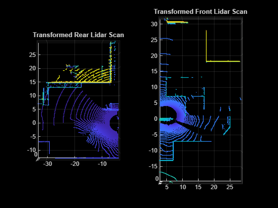
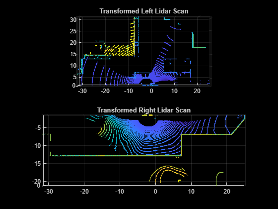
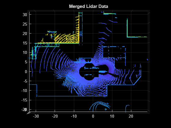
Transform the Lidar data points to a common origin and merge the processed data points into a single data set. Plot the transformed data.
[mergedPointCloud, alignedPointClouds] = exampleHelperMergeLidarPointClouds(exampleLidarPointClouds);
exampleHelperPlotRawLidarData(alignedPointClouds)
Plot the merged Lidar data points.
figure
pcshow(mergedPointCloud, ViewPlane="XY")
title("Merged Lidar Data")
Segment Lidar Data
Remove Excavator Model Detection Points from Lidar Data
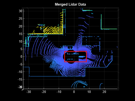
The merged Lidar data contains points that belong to the excavator. These points can result in false collision detection when used with the motion planner. Before proceeding to the motion planning step, remove these points from the Lidar data.
Create Bounding Boxes
To segment the excavator model detection points from the rest of the data, use bounding boxes around the various rigid bodies on the excavator model.
Use the maximum and minimum values of the mesh vertices of each rigid body of the excavator model to create a region of interest around the model. Apply an inflation region around the region of interest to capture any outlier points on the excavator.
% Set the rigid body tree configuration to the joint angles of the excavator arm set during the Lidar measurement
rbtState = deg2rad([0, 0, 0, 0]);

inflationRatio = 0.1; %inflate body size to catch edge cases
rbtBodies = excavatorRBT.Bodies;

% Loop over all the rigid bodies in the excavator model, get the visual
% mesh information. Create the region of interest as a matrix [xmin, ymin,
% zmin, xmax, ymax, zmax].
selfObjectROI = zeros(numel(rbtBodies), 6);
for ii=2:numel(rbtBodies)
    % Get transform of current body w.r.t to the base of the excavator
    tform_body = rigidtform3d(getTransform(excavatorRBT, rbtState, rbtBodies{ii}.Name));
    % Extract triangular mesh of current body
    vizData = getVisual(rbtBodies{ii});
    % Get the mesh points at the given transformation
    tri = transformPointsForward(tform_body, vizData.Triangulation.Points);

    % Get minimum and maximum points of the mesh to define the rectangular bounding box
    roi = ([min(tri); max(tri)]);

    % Inflate bounding box to catch edge points
    inflationFactor = inflationRatio*diff(roi);
    roi(1,:) = roi(1,:) - inflationFactor;
    roi(2,:) = roi(2,:) + inflationFactor;

    selfObjectROI(ii,:) = roi(:)';
end
Create a list of indices in the Lidar set that belong to the excavator model using findPointsInROI (Computer Vision Toolbox).
indicesSelfObject = [];
for ii=1:size(selfObjectROI,1)
    indicesSelfObject = [indicesSelfObject; findPointsInROI(mergedPointCloud, selfObjectROI(ii,:))];
end
With the indices of the excavator obtained in the previous step, use setdiff to create the set of indices belonging to the environment from the merged point cloud data.
indicesEnvironment = setdiff(uint32(1:mergedPointCloud.Count),indicesSelfObject);
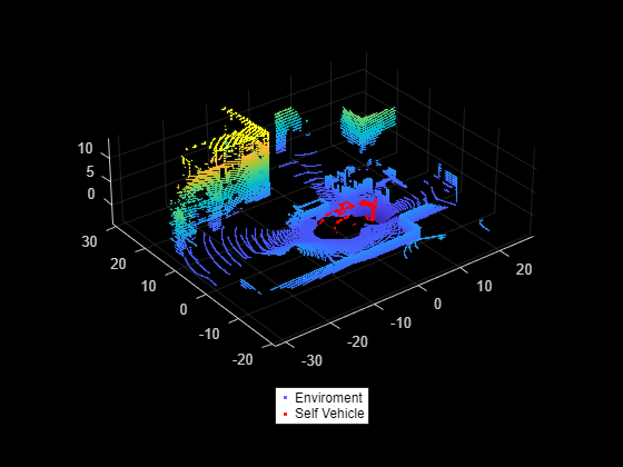
Use the indices of the points corresponding to the environment to create the environment point cloud and remove the outliers. The environmentPointCloud excludes the points belonging to the excavator model.
environmentPointCloud = select(mergedPointCloud, indicesEnvironment);
environmentPointCloud = pcdenoise(environmentPointCloud);
Visualize the environment point cloud and the excavator point cloud.
figure
pcshow(environmentPointCloud)
hold on
pcshow(select(mergedPointCloud, indicesSelfObject).Location,'r');
legend("Enviroment","Self Vehicle","Location","southoutside",Color=[1 1 1])
hold off
You can create an occupancyMap3D (Navigation Toolbox) object from the point cloud data and use it with motion planners to plan a collision-free path. occupancyMap3D requires a Navigation Toolbox™ license.
omap3D = occupancyMap3D(10);
pose = [0 0 0 1 0 0 0];
maxRange = 35;
insertPointCloud(omap3D, pose, environmentPointCloud, maxRange)
figure;
show(omap3D)
The Plan Collision-Free Path for Excavator Arm in MATLAB With Lidar Data example highlights motion planning with this point cloud data.
See Also
pointCloud | occupancyMap3D (Navigation Toolbox)