Simulate Earth Moving with Autonomous Excavator in Construction Site
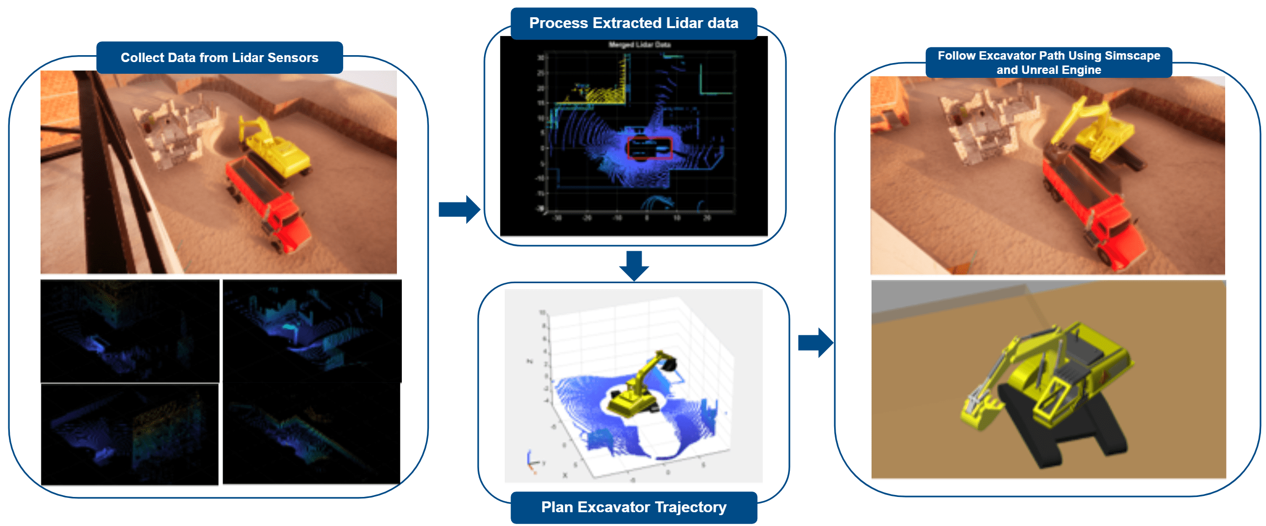
This example shows how to simulate earth moving workflows for an excavator by using Simulink®, in which you excavate the ground to create a depression and then move the spoil to a dump truck. This workflow has a modular design and you can modify it per your requirements.
To implement autonomy algorithms and perform simulation in Simscape™ Multibody™ and Unreal Engine™, you must install these toolboxes:
Robotics System Toolbox Offroad Autonomy Library™ — Simulate the dump truck in Simulink and Unreal Engine. For more details, see Install Robotics System Toolbox Offroad Autonomy Library Support Package.
Robotics System Toolbox™ — Model and simulate the excavator, and plan paths, and generate trajectories for multiple steps in the workflow in Simulink and Unreal Engine.
Simulink 3D Animation™ — Provide the Unreal Engine simulation environment.
Simscape™ Multibody™ — Simulate a high-fidelity excavator model using low-level controls.
Image Processing Toolbox™ and Computer Vision Toolbox™ — Visualize a point cloud using
pcshow(Computer Vision Toolbox) and merge multiple point clouds usingpcmerge(Computer Vision Toolbox).Navigation Toolbox™ — Represent the environment as an occupancy map with the
occupancyMap3D(Navigation Toolbox) object.Optimization Toolbox™ — Generate the trajectory using the
contopptrajfunction from Robotics System Toolbox.
This example integrates key concepts from several related examples. These examples provide pivotal workflows that are adapted into a cohesive simulation using Simulink.
Extract Scene From Lidar Data: Preprocess and merge Lidar data for creating an environment map.
Plan Collision-Free Path for Excavator Arm in MATLAB With Lidar Data: Plan path and generate trajectory following kinematic constraints for excavator arms.
Simulate Construction Vehicles in Unreal Engine for Material Handling: Prototype a construction scene with standard construction vehicles using ready-made assets.
Simulink Model Overview
Create the autonomous excavation workflow in Simulink by modeling the operations as blocks and subsystems. You can divide the modules based on their function or role and encapsulate each module in a subsystem with defined interfaces. In this example, the Simulink model is divided into high-level modules grouped by area. Each area contains subsystems depending on the required roles. Use the model to:
Process Perception Data to Understand Environment: Generate point clouds from Lidar data and convert them into a 3-D occupancy map to support motion planning, thereby creating an accurate representation of the environment for collision checking.
Plan Motion for Excavator: Use Stateflow to manage different stages and transitions of the autonomous excavation cycle. For each stage, plan a collision-free path using the rapidly exploring random tree (RRT) algorithm and generate an optimal trajectory that adheres to velocity and acceleration constraints for the excavator joints.
Control Excavator Motion: Use simple PID controllers to actuate pistons in the Simscape Multibody plant model to track desired joint angles and execute planned motion.
Simulate Excavator and Construction Site: Simulate the excavator using Simscape Multibody and the environment using Unreal Engine. Include additional actors like stationary dump trucks or other objects to add context to the simulation.
open_system("followPlannedTrajectorySimscapeUnreal.slx");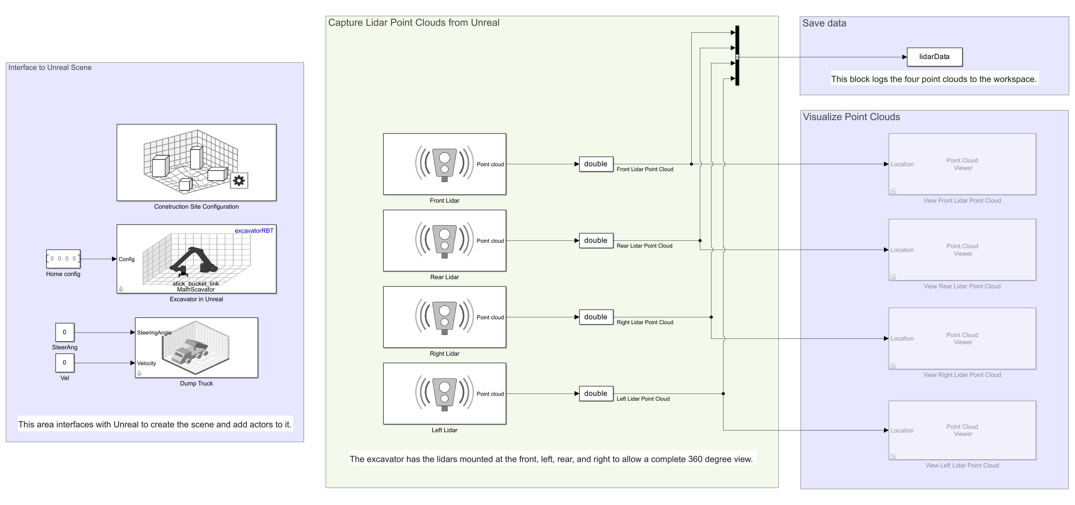
Initial Setup
Download Dependencies
To run the example, download the construction site scene for Unreal Engine and an excavator model for Simscape. You can download these dependencies using helper files provided with this example. The helpers check if these files are available locally, otherwise they download them.
helperDownloadConstructionScene
Construction site scene file available locally
helperDownloadExcavatorDesign
Adding ExcavatorDesignWithSimscape to MATLAB path ...OK
You can inspect other parameters used by the Simulink model by examining the base workspace and the Simulink Data Dictionary file. For more information on a data dictionary, see What Is a Data Dictionary? (Simulink)
do = open("EarthMoving.sldd")
Create Robot Model from CAD Data
The excavator design originally came from a CAD model, which is used in three places:
A Simscape model that adds hydraulics to the rigid body dynamics for a complete physical model
A kinematic model for collision checking and motion planning
An Unreal Engine visualization that simulates the motion of the excavator
While there are many ways to provide the CAD model to these various parts, this example executes this workflow:
The Simscape model uses blocks from Simscape Multibody to add the dynamics to create a plant model for the excavator. The excavator joints are passive revolute joints which use pistons for actuation. File Solid (Simscape Multibody) block imports the CAD files to model the excavator body part. Cylindrical Joint (Simscape Multibody) block and Universal Joint (Simscape Multibody) block are used to model pistons. The controller in this example manages only the mechanical aspects of the excavator. However, you can use this model to test a more advanced controller that regulates the hydraulic systems. For more information about designing Simscape Multibody models, see Heavy Equipment Design with Simscape.
The kinematic model was created by extracting a URDF file from SolidWorks®, using a third-party tool and importing it as a
rigidBodyTreeobject in MATLAB. The CAD files are converted to STL formats. You can load the URDF file into MATLAB usingimportrobotto create arigidBodyTreeobject and use it to Plan Collision-Free Path for Excavator Arm in MATLAB With Lidar Data. You can find one of the tools for conversion in this resource.There are several ways to import to Unreal Engine. You can reuse a
rigidBodyTreeobject that is used for kinematic modeling by using the Simulation 3D Robot block. This step enables excavator motion simulation in Unreal Engine with minimal additional effort.
Process Perception Data to Understand Environment
Process Lidar Data
This section describes how to create a merged point cloud for a unified view of the environment. You can find a comprehensive overview of the of the process to create a merged point cloud in the Extract Scene From Lidar Data example in MATLAB. In this example, you use four point clouds in the sensor frame, captured from the right, front, left, and rear of the excavator. You then transform the point clouds into the excavator frame of reference, removing the points that appear due to reflections from the excavator itself, and merge them into one by using pcmerge (Computer Vision Toolbox).
This example employs a similar approach in the Process Lidar Data subsystem, where the data is processed at the run time during model execution. You can integrate the post-processing performed in MATLAB in to Simulink using the MATLAB System (Simulink) block. This is a resource heavy operation and does not need to be performed at every time step. You can place the MATLAB System block inside a Function-Call Subsystem (Simulink), which is triggered when you trigger the Trajectory Planner subsystem and during initialization.
You can capture the lidar data during simulation using four Simulation 3D Lidar (Simulink 3D Animation) blocks and output them over a bus. The Process Lidar Data subsystem uses the bus as input and outputs the merged point cloud as a NumPoints-by-3 matrix signal. Convert the merged point cloud into an occupancyMap3D in the Plan Trajectory for Excavator section for checking collisions with obstacles.

Extract Information for Excavation Site
You can extract information regarding the current site from the sensor data, such as dump truck location and excavator configuration. This example uses mock modules to show the workflow by relying on the ground truth from Unreal Engine. You can replace them with modules, such as object detection and localization, that process sensor information to compute the pose of salient locations.
Plan Motion for Excavator
This section explains how to plan motion for the different stages of the excavation cycle. To model the cycle, you can divide this module into two key sub-modules — Manage Tasks for Autonomous Excavation Cycle, which utilizes Stateflow to monitor the excavator's current state and make task delegation decisions, and Plan Trajectory for Excavator, which includes path planner and trajectory generator to effectively plan the excavator's motion. Together, these sub-modules ensure efficient and autonomous operation of the excavator by seamlessly coordinating task management and motion planning.
Manage Tasks for Autonomous Excavation Cycle
This section implements a task manager in Stateflow to coordinate the various states and transitions within a system. It ensures that tasks are executed in the correct order and handles decision-making processes efficiently.
To initialize the scene, send out an output event to trigger the Perception module. The Perception module extracts information related to the site from the latest lidar and ground truth data available from Unreal Engine.
This example uses states to represent each stage. To manage excavation cycle, you can simulate the following states subsequently:
Excavation: Operate the bucket and arm to dig into the soil and gather it in the bucket (end-effector).
GoToDump: Move the arm to the top of the dump truck.
Dump: Open the bucket to drop the spoil.
GoToExcavation: Move the arm back to the top of the excavation site.

To trigger the Process Lidar Data and Trajectory Planner subsystems during the stages, you can use output events. To learn more about events in Stateflow, see Synchronize Model Components by Broadcasting Events (Stateflow).
To successfully trigger the Trajectory Planner subsystem, the PlanObject signal must output based on whether the trajectory is for the arm or the bucket, depending on the current stage in the cycle. If the trajectory planning is not successful, continue until a satisfactory result is achieved or the maximum number of attempts is reached.
Successful trajectory generation transitions the task manager to a state where it waits for the controller to move the excavator arm to the goal, such as reaching the dump location. The controller operates at every time step, while the task manager waits for the ReachedGoal signal to transition to the next state. If the controller fails to reach the goal within the specified value of the controllerTimeOut parameter, the task manager exits the simulation.
open(Simulink.BlockPath("followPlannedTrajectorySimscapeUnreal/Excavator Task Manager"), OpenType='new-tab')
Plan Trajectory for Excavator
Plan trajectory for the excavator using a path planner and a trajectory generator. You can find a comprehensive overview of motion planning in MATLAB in Plan Collision-Free Path for Excavator Arm in MATLAB With Lidar Data. The MATLAB example shows how to create the occupancyMap3D from the merged point cloud, plan a path that avoids obstacles using manipulatorRRT, and generate a trajectory that follows kinematic constraints using contopptraj.
This example employs a similar approach in Simulink within the Trajectory Planner, a Function-Call subsystem triggered at the beginning of each stage in the excavation cycle. The two most significant steps from the MATLAB example, Path Planning and Path to Trajectory Conversion, are implemented in Simulink in this example using MATLAB System blocks. In addition to path planning using RRT and trajectory generation, this example also includes a simple planner, detailed in Path planning for Selected Object. This example also moves the arm from the drop location to the excavation location to close the loop, whereas the MATLAB example shows only the movement from the excavation to the drop location.
In this example, the Trajectory Planner subsystem uses the current excavator joint angles and the goal joint angles as input alongside a representation of the environment as a lidar point cloud. A configuration represents a specific arrangement of the excavator arm, defined by the unique joint angles between the chassis, boom, stick, and bucket. In this section, you convert the merged lidar point cloud generated in Process Lidar Data into an occupancyMap3D to efficiently check for collisions.
open(Simulink.BlockPath("followPlannedTrajectorySimscapeUnreal/Trajectory Planner"), OpenType='new-tab')

Path Planning for Selected Object
Different states in the excavation cycle present different requirements for path planning. Excavation and dropping primarily requires bucket operation without any need for collision checking. Whereas, the whole arm is required to move to the dump site or excavation site, which requires obstacle avoidance. This example uses two path planners: manipulatorRRT with rigidBodyTree is used for operating the arm, and a simple planner that concatenates start and goal for operating the bucket. Value on the input port Selected Object determines which planner gets executed. For this example, the Task Manager module sets the appropriate value when it enters a state in the cycle.
RRT Path Planner: This planner uses an RRT algorithm. It is a sampling-based planner, that you can use to model systems that can be modeled with a
rigidBodyTreeobject. The planner in this example skips self collisions and and avoid collisions with obstacles represented usingoccupancyMap3D. The arm must not be in a configuration that can cause the bucket to drop the spoil. To avoid such a configuration the joint angles are restricted for joints between chassis-boom and boom-stick. If the bucket should remain stationary, as indicated by the same joint angle at both the start and goal configurations, then the joint angle between the stick and the bucket is restricted to within 0.1 radians above and below this specified joint angle.Simple Planner: This planner directly connects the start and goal for operating the bucket, as collision checking is unnecessary at this stage. Checking for collisions can raise incorrect alerts since the bucket is expected to be in contact with the ground while collecting spoil.
Generate Trajectory
Using the path planned in the previous step, contopptraj generates a fixed number of configurations with their corresponding time stamps while adhering to velocity and acceleration limits. The contopptraj function uses a solver that computes a time-optimal trajectory subject to kinematic constraints using the TOPPRA algorithm. This subsystem generates a collision-free trajectory that moves the object to the goal as fast as possible.
Select Reference Configuration
After generating the trajectory, select a reference configuration at every time step and send it to the Controller module. Select the reference configuration based on the trajectory time stamps and the current simulation time.
open(Simulink.BlockPath("followPlannedTrajectorySimscapeUnreal/Select Reference Configuration"), OpenType='new-tab')
Control Excavator Motion
Once the trajectory is generated, you can control joint angles by setting the actuator values in the Simscape Model for the excavator. This example shows a simple path-tracking controller for the excavator arm that is designed to control the mechanics of the excavator. However, you can use this model to test a more advanced controller that regulates hydraulic systems.
The controllers manage the excavator actuators using two distinct approaches:
The swing motor directly maps the desired state from the planned trajectory to the joint state. This design eliminates the need for additional controllers and is particularly useful for testing the simulation framework during early development stages without incorporating complex algorithms.
Use a multi-input, multi-output (MIMO) PI controller to command the hydraulic pistons for the arm, which includes the boom, stick, and bucket (end-effector). The controller takes the desired and current joint angles as inputs and outputs actuator positions to achieve the target joint angles. To initialize the PI controller with the correct piston values, use
helperIKForExcavatorscript for inverse kinematics computation.
open(Simulink.BlockPath("followPlannedTrajectorySimscapeUnreal/Control Exavator Arm"), OpenType='new-tab')
Simulate Excavator and Construction Site
Simulate Scene with Unreal Engine
Simulate the environment and actors in it using Simulation 3D Animation and Unreal Engine. You can visualize the motion of the actors, collisions, and other errors that occur during trajectory execution.
The Interface with Unreal subsystem simulates:
Construction Site Scene using the Simulation 3D Scene Configuration (Simulink 3D Animation) block by setting the Scene source to
Default Scenesand Scene name toConstruction site scene.

Dump Truck using the Simulation 3D Physics Dump Truck block, which is included in the Offroad Autonomy Library support package. Use the block to import dump truck Unreal assets into the construction scene. Set the
SteeringAngleandVelocityinputs to zero to keep the dump truck stationary, reflecting real-world conditions.Excavator using the Simulation 3D Robot. This block adds the excavator as a
rigidBodyTreeobject to the construction scene in Unreal Engine. Use the block to visualize the joint configuration generated from theExcavator Simscape Modelsubsystem.Lidar sensor using four Simulation 3D Lidar blocks. Use these blocks to capture the environment from right, front, left, and rear of the excavator. Process Lidar Data utilizes the generated data to make it suitable for Plan Trajectory for Excavator.
open(Simulink.BlockPath("followPlannedTrajectorySimscapeUnreal/Interface with Unreal"), OpenType='new-tab')
Simulate Excavator Motion Using Simscape Model
The excavator model in this example is adapted from the Excavator Design with Simscape example. It incorporates CAD files using File Solid (Simscape Multibody) block to represent the excavator body and uses other Simscape Multibody blocks to simulate its dynamics. This example models the excavator with passive revolute joints using the Revolute Joint (Simscape Multibody) block. The pistons actuating these joints are modeled using Cylindrical Joint (Simscape Multibody) and Universal Joint (Simscape Multibody) blocks to facilitate realistic movement. For more information, see Heavy Equipment Design with Simscape.

The excavator model requires the inputs listed in this table to simulate motion.
Bus element | Description |
|---|---|
| A bus with three elements px, py, pz, that define excavator base position with respect to the world frame. |
| Swing motor angle that controls joint angle between the chassis and base. |
| Boom piston position that controls joint angle between the boom and chassis. |
| Stick piston position that controls joint angle between the stick and boom. |
| Bucket piston position that controls joint angle between the bucket and stick. |
The output bus contains joint position and forces read from the actuator sensors.
open(Simulink.BlockPath("followPlannedTrajectorySimscapeUnreal/Excavator Simscape Model"), OpenType='new-tab')
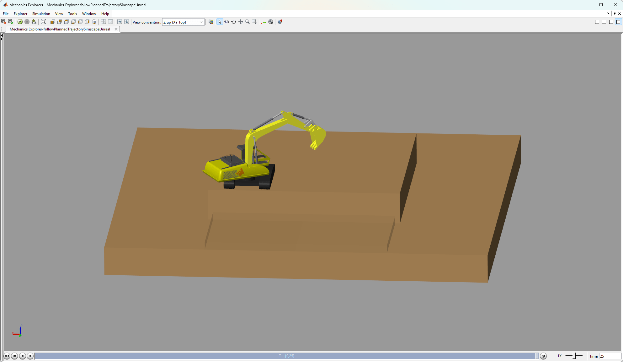
Simulate Complete System
Simulate the complete system and validate the planned trajectories. To simulate and visualize the scene in Unreal Engine and Simscape Multibody Mechanics Explorer, click Run on the Simulation tab of the Simulink toolstrip.
sim("followPlannedTrajectorySimscapeUnreal.slx");
This example tracks the trajectory of an excavator using motion planners, enhancing controller design through high-fidelity simulation and realistic visualization with Unreal Engine. The workflow focuses on automating the excavator to move the spoil from the ground to a dump truck. Offroad Navigation for Autonomous Haul Trucks in Open Pit Mine shows an extended workflow to autonomously navigate the haul truck to the dump site.
The Simulate Construction Vehicles in Unreal Engine for Material Handling example provides a related workflow in which you can quickly prototype a construction scene with standard vehicles using ready-made assets. In this example, a backhoe loads bricks into a dump truck.