分析包含计数器和计时器的模型
如果您的模型包含 counter 或 timer 模块,Simulink® Design Verifier™ 分析会搜索状态序列,以查找满足特定目标的输入值。该分析会优先考虑可以在较少时间步内实现的配置。较长的计时器和计数器会导致分析必须涵盖大量状态,尤其是在涉及时滞或倒计时的情况下。模型中存在计时器和计数器会显著影响使用 Simulink Design Verifier 进行模型分析的复杂度和持续时间。分析包含较长计数器和计时器的模型时面临的一些挑战:
状态爆炸,当较长计时器或计数器大幅增加分析必须覆盖的状态数量时发生
延迟响应,例如滤波或平均值计算,这会增加所需的计时器步数,并导致测试用例更长
启用运行穷举分析参数后,当您的模型在 Stateflow® 图中包含计时器时,会导致死逻辑检测分析耗费大量的时间
建模模式及其对分析的影响
不同的建模模式会以不同的方式影响 Simulink Design Verifier。例如,在控制系统中,去抖等模式用于管理对特定条件的响应。控制器会等待指定的时间段,直到出现特定条件。
一个在 delay 模块的输出端连接了 scope 模块的计数器显示值如何增加直至变为 10,此时满足决策目标。从初始状态开始,当计数器进入计时器激活状态时,它会在计时器进度区域中暂停指定的持续时间,然后再执行新操作。
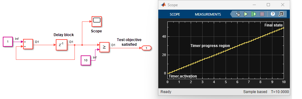
Simulink Design Verifier 会遍历一系列状态,以识别能使分析达到满足测试目标的状态的输入值。计时器模式在计时器进度区域中创建扩展的状态序列,因此会使这一过程变得复杂。这样一来,分析很难满足计时器进度区域之后发生的测试目标。您在分析过程中使用的建模风格会使检测此类模式变得复杂。
| 建模模式和描述 | 对测试目标的影响 |
|---|---|
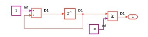
| 计数器:跟踪事件发生的次数或操作执行的次数。有关计数器的详细信息,请参阅Counter Free-Running。 | 关系模块的决策目标 - 输出为 true。只有在对模型进行 10 步仿真后,才能满足此目标。
|
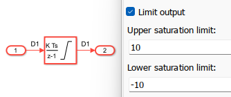
| 积分器:随着时间的推移,值会不断累积。累积的值通常会饱和处理为阈值内的边界值。有关积分器的详细信息,请参阅Integrator。 | 饱和界限的决策目标。为了满足积分器模块的决策目标(积分结果 > 饱和上限),可能需要完成一些步数,直到输入信号的值累积到界限为止。
|
| 上升沿或下降沿:检测从低状态到高状态的转换。持续时间会影响上升沿或下降沿。有关详细信息,请参阅Detect Change。 | 检查子系统内的目标。上升沿触发器要求触发器的输入过零。因此,缓慢变化的输入可能需要更多的步数才能过零。
|
| MATLAB® 函数中的计数器:在 MATLAB 函数中使用计数器,可通过在循环语句或条件语句中递增的简单变量来实现。 | 分支 function y = fcn(u) persistent counter; if isempty (counter) counter = 0; end counter = counter + 1; y = 0; if (counter > 10) counter = 0; if (u > 0) y = 1; end end end |
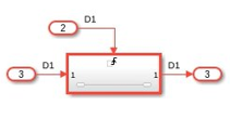
| Stateflow® 中的计时器模式:执行函数之前等待指定的时间。有关详细信息,请参阅使用去抖逻辑减少瞬变信号 (Stateflow)。 | 决策目标达到状态 S5。该目标受时序条件
|

使用计时器和计数器优化对模型的 Simulink Design Verifier 分析
您可以使用一些解决方法来管理在模型中使用计时器和计数器进行 Simulink Design Verifier 分析所引发的复杂性。基本解决方法包括:
| 场景 | 建议的操作 | 分析行为 |
|---|---|---|
首次执行分析以获得覆盖率。 | 不适用 | 分析使用内部启发式方法自动检测并通过计时器进度区域。有关详细信息,请参阅对大型模型进行分析。 |
检测在计时器进度区域之后可达的模型意外行为。 |
| 分析可以快速通过计时器进度区域,并分析设计中超出该区域的状态,以检查意外行为。 注意 如果系统在时滞设为 2000 步时出现逻辑错误,则在时滞更改为 2 秒时也会出现相同的错误。
|
针对受计时器影响的目标。 | 将计数器和计时器的初始值设置为 Simulink Design Verifier 分析可以调整的参数,从而缩短测试用例。 | 分析会选择能使较短测试用例超过阈值的初始值。有关详细信息,请参阅应用参数配置后扩展现有测试用例。 |
如果您有受计时器影响的未决目标并且想要重新运行分析,可使用这些解决方法。
| 建议的操作 | 分析行为 |
|---|---|
执行 | 分析会使用其他计时器检测启发式方法进行计时器检测。有关详细信息,请参阅 |
使用穷举计时器或计数器的现有测试用例,并对其进行扩展以形成一个全面的测试套件。 | 分析会使用现有的测试输入作为起点。它会直接跳转至仿真此输入后可达的状态序列。有关详细信息,请参阅扩展现有测试套件。 |
添加自定义测试目标作为中间步,以满足未解决的目标。 | 满足这些自定义目标后,分析会达到可以满足未解决目标的状态。 |
| 分析会选择能使较短测试用例超过阈值的初始值。有关详细信息,请参阅应用参数配置后扩展现有测试用例。 |
另请参阅
sldvtimer | 扩展现有测试套件 | Counter Free-Running | Integrator