HDL Implementation of SISO Fading Channel
This example shows how to use a Simulink® model of a single-input, single-output (SISO) fading channel. You can use this example to evaluate the performance of wireless communication systems over Rayleigh and Rician fading channels. The Simulink blocks in this example are optimized for HDL code generation and hardware implementation. The HDL capabilities of this example can speed up the performance evaluation using hardware-in-the-loop simulation. For more information, see [ 1 ].
You can use this example in conjunction with the HDL OFDM Transmitter and HDL OFDM Receiver examples.
Introduction
Modern wireless communication systems include different types of fading channel models, such as pedestrian-A, pedestrian-B, vehicular, and extended typical urban (ETU). Evaluating the performance of wireless communication systems with these channel models is challenging. In wireless communication, you can accurately model the channel using a complex Gaussian distribution. If the model has no line-of-sight component, then the Gaussian process has zero mean and its envelope is Rayleigh distributed. If the model has a line-of-sight component, then the Gaussian process has nonzero mean and its envelope is Rician distributed. The line-of-sight path is characterized by the K-factor in a Rician distribution.
Model Architecture
This figure shows the high-level architecture block diagram of the SISO fading channel implementation.

This architecture comprises three modules:
Generate Complex Channel Coefficients — Generate Gaussian variables for the real and imaginary parts of the channel. Calculate the complex channel coefficients using the channel characteristics comprising discrete path delays, average power gains, normalize average path gains, fading distribution, and K-factors as well as the Gaussian random variables.
Perform FIR Filtering — Filter the modulated input symbols with the generated complex channel coefficients and return the faded symbol.
Plot PDF Of Fading Distribution — Compute the envelope of the complex channel coefficients and plot the probability density function (PDF) of the fading distribution.
Note: The channel coefficients vary at a fixed interval equal to the maximum path delay, which is set to eight samples. The path delays are specified in samples as integers.
This figure shows the top-level structure of the HDLFadingChannel model. You can generate the HDL code for the SISO Fading Channel subsystem in this model.
modelname = 'HDLFadingChannel';
open_system(modelname);
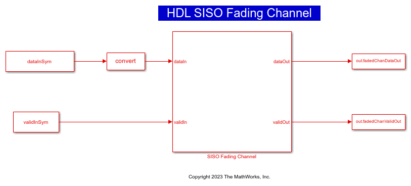
The top-level structure of the model includes the Complex Channel Coefficients Generator and FIR Filter subsystems.
% Open the subsystems inside the |SISO Fading Channel| model.
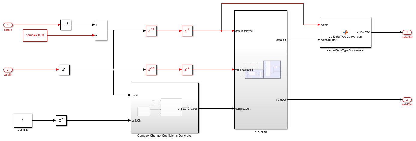
open_system([modelname '/SISO Fading Channel'],'force');
Complex Channel Coefficients Generator
The Complex Channel Coefficients Generator subsystem comprises Gaussian Random Variable Generator and Complex Channel Calculator subsystems.
Gaussian Random Variable Generator— Generate two independent Gaussian random variables, one for the real part and the other for the imaginary part, using the Box-Muller transform. Each random variable has zero mean and unit variance. For more information, see HDL Implementation of AWGN Generator.
Complex Channel Calculator— Calculate complex channel coefficients. This subsystem contains theGenerate Multiplication and Addition FactorandCompute Product and Summationsubsystems. TheGenerate Multiplication and Addition Factorsubsystem accepts the discrete path delay in samples, average path gains in dB, normalization, fading distribution, and K-factor from the mask parameters and validCh signal through input port. This subsystem converts average path gains from dB to a linear scale. Select the Normalization parameter to normalize the gain by dividing each average path gain with the sum of the average path gains. For the Rayleigh fading distribution, this subsystem calculates the multiplication factor using the average path gain and sets the addition factor to 0. For the Rician fading distribution, this subsystem calculates the multiplication and addition factors using the average path gain and K-factor. The subsystem serializes and returns multiplicationFactor and additionfactor signals based on the discrete path delay values using a counter enabled by validIn signal. TheCompute Product and Summationsubsystem multiplies the dataGaussRe and dataGaussIm signals with the multiplicationFactor signal and returns the complex coefficients. Further, this subsystem computes the sum of additionFactor signal and the complex coefficients to provide the complxChanCoeff signal.
FIR Filter
The FIR Filter subsystem converts the scalar complex channel coefficients into a vector with a length equal to maximum discrete path delay. Further, this subsystem filters the input data with the vector channel coefficients using the Discrete FIR Filter block to provide the faded output symbols.
Configure Channel
Set up the channel parameters. For discrete path delays, specify a row-vector of nonnegative integers in ascending order. Each value indicates the relative delay of samples from the first path. You can calculate discrete path delays in samples by multiplying path delay by sampling rate. Resource usage is high for a larger number of samples. Specify the K-factor as a positive scalar or a vector. To enable this parameter, set the Fading distribution parameter to Rician. When you specify a scalar, the first discrete path behaves according to a Rician fading process and the remaining discrete paths behave according to independent Rayleigh fading processes. When you specify a vector, the discrete paths corresponding to nonzero elements behave according to Rician fading processes and any zero elements behave according to Rayleigh fading processes.
discretePathDelays =  [0 2 4 8];     % Discrete path delays (in samples)
avgPathGainsdB     =  [0 -3 -6 -12]; % Specify average path gains (in dB)
normAvgPowTo0dB    =  true;          % Normalize average path gains to 0 dB
fadingDistri = 'Rician';             % Fading distribution: 'Rayleigh' or 'Rician'
if strcmp(fadingDistri,'Rician')
    KFactor = [3 0 0 2.5];           % If K-factor is 0, distribution type is Rayleigh.
else
    KFactor = 0;
end
if normAvgPowTo0dB
    set_param('HDLFadingChannel/SISO Fading Channel','normPathGain','on')
else
    set_param('HDLFadingChannel/SISO Fading Channel','normPathGain','off') %#ok<UNRCH>
end
set_param('HDLFadingChannel/SISO Fading Channel','fadingDistri',fadingDistri)
Generate Input Data
Generate random bits using the randi function and perform QPSK modulation using the pskmod function to obtain the input data.
numSymbols = 10^(6);              % Number of modulated input symbols
modOrder = 4;                     % Order of modulation
symMap = [0 2 3 1];               % Symbol mapping
phaseOffset = pi/4;               % Phase offset
nBitsPerSym = log2(modOrder);     % Number of bits per symbol
numBits = numSymbols*nBitsPerSym; % Total number of input bits used
inpBits = randi([0 1],numBits,1); % Input bit generation
dataInSym = pskmod(inpBits,modOrder,phaseOffset,symMap,'InputType','bit'); % Input symbols
validInSym = boolean([ones(1,numSymbols)]); % Input valid
simTime = numSymbols + 100;
Run Simulink Model
Simulate the HDLFadingChannel model and collect the faded output symbols when the validout signal is high.
out = sim('HDLFadingChannel');
fadedComplxSym = out.fadedChanDataOut(out.fadedChanValidOut);
Results and Plots
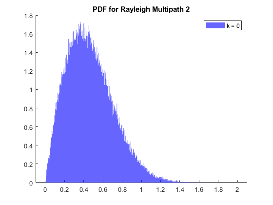
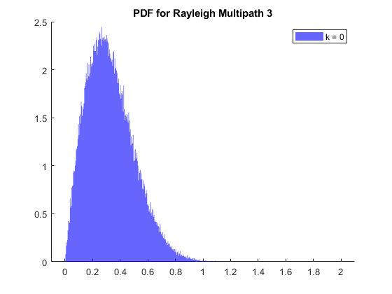
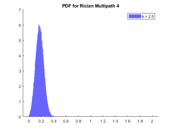
Collect the complex channel coefficients from the chanScalIn signal when the chanValid signal is high. Calculate the channel length using discrete path delays. You can form the channel matrix with a number of rows equal to the greatest integer less than the quotient. Calculate the quotient value by dividing the number of complex channel coefficients with the channel length. The number of columns is equal to the channel length. Plot the PDF using the histogram object applied to the absolute value of each column corresponding to the discrete path delays.
squeezeChOut = squeeze(out.chScalar);
repmatChValid = squeeze(out.chScalarValid);
reqdChValid = repmatChValid.';
chCoeff = squeezeChOut(boolean(reqdChValid));
[chCoeffRows,~] = size(chCoeff);
channelLength = discretePathDelays(end) + 1; % Calculate channel length
chanMatRowSize = floor(chCoeffRows/channelLength);
chanSize = chanMatRowSize*channelLength;
chanMatrix = reshape(chCoeff(1:chanSize),channelLength,chanMatRowSize).';

% Plot PDF
close all;
fadProbDist = get_param('HDLFadingChannel/SISO Fading Channel','fadingDistri');
if strcmp(fadProbDist,'Rician')
    if length(KFactor) < length(discretePathDelays)
        KFactor = [KFactor zeros(1,length(discretePathDelays)-length(KFactor))];
    end
    for pathNum = 1:length(discretePathDelays)
        if KFactor(pathNum)
            fadStr = 'Rician';
        else
            fadStr = 'Rayleigh';
        end
        figure (pathNum)
        str = sprintf('PDF for %s Multipath %d',fadStr,pathNum);
        title(str)
        hold on
        histogram(abs(chanMatrix(:,discretePathDelays(pathNum)+1)),500,...
            'Normalization','pdf','BinLimits',[0 2],'FaceColor','blue', ...
            'EdgeColor','none');
        strLeg = sprintf('k = %s',num2str(KFactor(pathNum)));
        legend(strLeg);
    end
else
    for pathNum = 1:length(discretePathDelays)
        figure (pathNum)
        str = sprintf('PDF for Rayleigh Multipath %d',pathNum);
        title(str)
        hold on
        histogram(abs(chanMatrix(:,discretePathDelays(pathNum)+1)),500,...
            'Normalization','pdf','BinLimits',[0 2],'FaceColor','blue', ...
            'EdgeColor','none');
    end
end

Verify Channel Output
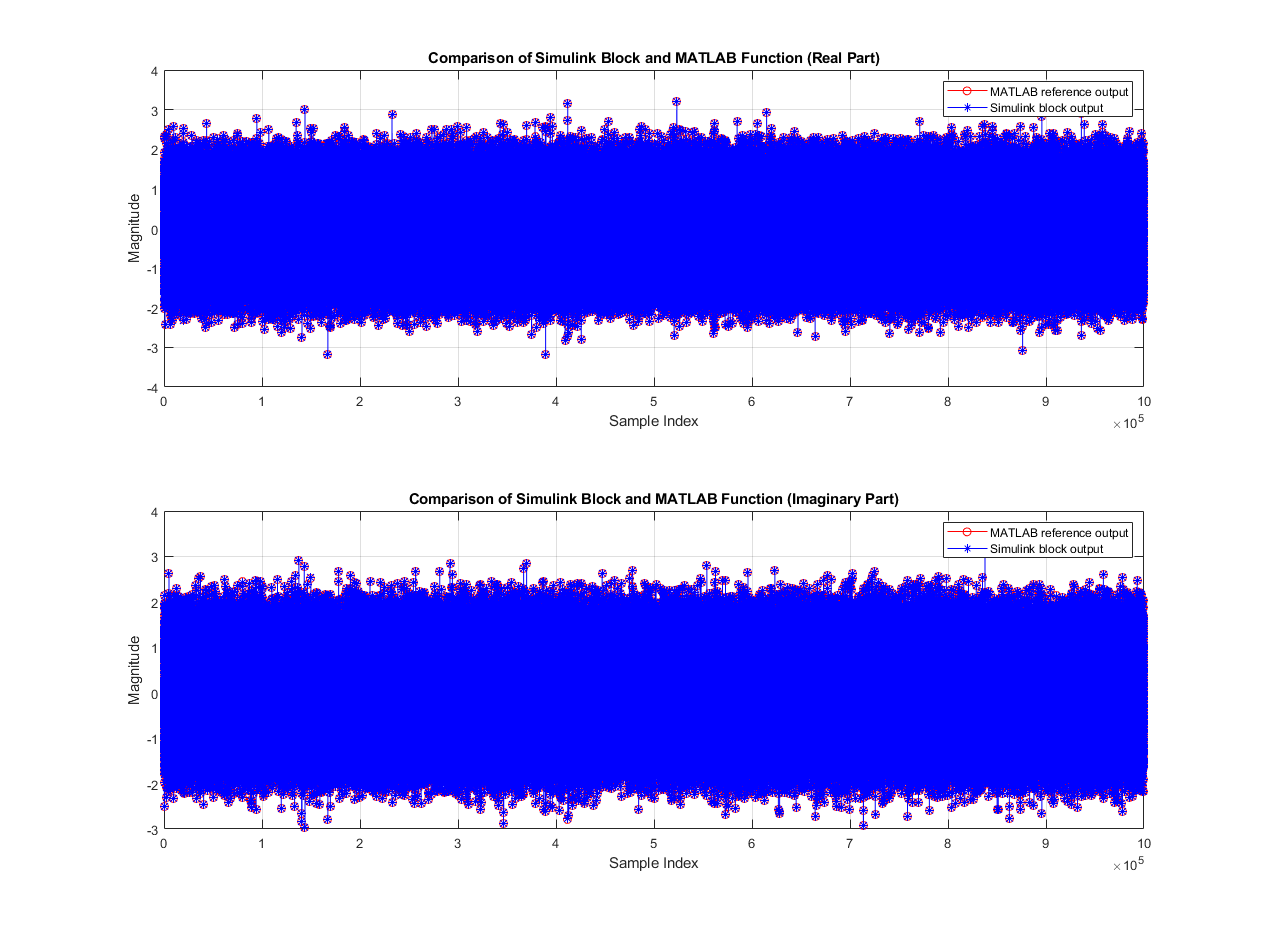
Compare the output of the SISO Fading Channel subsystem with the output of the HDL equivalent fading channel MATLAB function.
% MATLAB output
fprintf('\n Simulating MATLAB HDL Fading for comparison...\n');
fadedComplxSymMatlab = hdlFadingChan(dataInSym,discretePathDelays,avgPathGainsdB,normAvgPowTo0dB,fadingDistri,KFactor);
fprintf('\n Simulation complete. \n')

% Compare MATLAB and Simulink outputs
figure('units','normalized','outerposition',[0 0 1 1])
subplot(2,1,1)
plot(real(fadedComplxSymMatlab(:)),'-ro');
hold on;
plot(real(fadedComplxSym(:)),'-b*');
grid on
legend('MATLAB reference output','Simulink block output')
xlabel('Sample Index')
ylabel('Magnitude')
title('Comparison of Simulink Block and MATLAB Function (Real Part)')

subplot(2,1,2)
plot(imag(fadedComplxSymMatlab(:)),'-ro');
hold on;
plot(imag(fadedComplxSym(:)),'-b*');
grid on
legend('MATLAB reference output','Simulink block output')
xlabel('Sample Index')
ylabel('Magnitude')
title('Comparison of Simulink Block and MATLAB Function (Imaginary Part)')

sqnrRealdB = 10*log10(double(var(real(fadedComplxSym(:)))/abs(var(real(fadedComplxSym(:)))-var(real(fadedComplxSymMatlab(:))))));
sqnrImagdB = 10*log10(double(var(imag(fadedComplxSym(:)))/abs(var(imag(fadedComplxSym(:)))-var(imag(fadedComplxSymMatlab(:))))));

fprintf('\n HDL Fading Channel output \n SQNR of real part: %.2f dB',sqnrRealdB);
fprintf('\n SQNR of imaginary part: %.2f dB\n',sqnrImagdB);
 Simulating MATLAB HDL Fading for comparison...

 Simulation complete.

 HDL Fading Channel output
 SQNR of real part: 38.09 dB
 SQNR of imaginary part: 38.05 dB
Generate HDL Code
To check and generate the HDL code referenced in this example, you must have an HDL Coder™ license.
To generate the HDL code, enter this command at the MATLAB command prompt.
makehdl('HDLFadingChannel/SISO Fading Channel')
To generate a test bench, enter this command at the MATLAB command prompt.
makehdltb('HDLFadingChannel/SISO Fading Channel')
Synthesize the HDLFadingChannel subsystem on a Xilinx Zynq® UltraScale+ RFSoC xczu29dr-ffvf1760-2-e. This table shows the resource utilization results.
F = table(...
    categorical({'CLB LUTs';'CLB Registers';'RAMB36';'DSP'; ...
    'Max. Frequency (MHz)'}) ,...
    categorical({'9220';'7993';'4';'56';'323.80'}), ...
    'VariableNames',{'Resources','Values'});

disp(F);
         Resources          Values
    ____________________    ______

    CLB LUTs                9220
    CLB Registers           7993
    RAMB36                  4
    DSP                     56
    Max. Frequency (MHz)    323.80
References
Alimohammad Amirhossein, Saeed Fouladi Fard, and Bruce F. Cockburn. "Hardware Implementation of Rayleigh and Ricean Variate Generators, "IEEE Transactions on Very Large Scale Integration (VLSI) Systems, vol. 19, no. 8, pp. 1495-1499, August 2011. https://doi.org/10.1109/TVLSI.2010.2051465.