对 16-QAM 信号使用脉冲整形
此示例对使用 MATLAB 检查 16-QAM示例进行了扩展,以通过使用一对平方根升余弦 (RRC) 滤波器执行脉冲整形和升余弦滤波。rcosdesign 函数创建滤波器。通过向通信链路添加前向纠错 (FEC) 可以改进 BER 性能。要向包含脉冲形状滤波的通信链路添加 FEC,请参阅对 16-QAM 信号使用前向纠错示例。
此示例说明如何使用由基带调制器、信道、解调器以及脉冲整形和升余弦滤波组成的通信链路处理二进制数据流。该示例计算误码率 (BER),在眼图中显示滤波效果,并在星座图中显示发射信号和接收信号。
建立仿真框架
为具有升余弦滤波和 AWGN 信道的 16-QAM 调制方案定义仿真参数。
M = 16;            % Modulation order
k = log2(M);       % Bits per symbol
numBits = k*7.5e4; % Bits to process
sps = 4;           % Samples per symbol (oversampling factor)
创建 RRC 滤波器
设置 RRC 滤波器参数。
filtlen = 10;      % Filter length in symbols
rolloff = 0.25;    % Filter rolloff factor
使用 rcosdesign 函数创建一个 RRC 滤波器。
rrcFilter = rcosdesign(rolloff,filtlen,sps);
使用 impz 显示 RRC 滤波器冲激响应。
impz(rrcFilter)

计算系统 BER
使用 randi 函数生成随机二进制数据。将 rng 函数设置为其默认状态或任何静态种子值,以便示例产生可复现的结果。
rng default;                     % Default random number generator
dataIn = randi([0 1],numBits,1); % Generate vector of binary data
使用 bit2int 函数将 k 元组二进制字转换为整数符号。
dataSymbolsIn = bit2int(dataIn,k);
使用 qammod 函数应用 16-QAM 调制。
dataMod = qammod(dataSymbolsIn,M);
使用 upfirdn 函数按过采样因子对信号进行上采样并应用 RRC 滤波器。upfirdn 函数会在上采样信号末尾填充零,以刷新滤波器。然后,该函数应用该滤波器。
txFiltSignal = upfirdn(dataMod,rrcFilter,sps,1);
使用每符号的位数 (k)、每符号的采样数 (sps) 和 convertSNR 函数,将每比特能量与噪声功率谱密度之比 (EbNo) 转换为 SNR 值,以供 awgn 函数使用。
EbNo = 10;
snr = convertSNR(EbNo,'ebno', ...
    samplespersymbol=sps, ...
    bitspersymbol=k);
使滤波后的信号通过 AWGN 信道。
rxSignal = awgn(txFiltSignal,snr,'measured');对接收信号使用 upfirdn 函数以对信号进行下采样和滤波。使用与对发射信号上采样应用的相同过采样因子进行下采样。使用与对发射信号应用的相同 RRC 滤波器进行滤波。
每个滤波运算将信号延迟符号中滤波器长度的一半,即 filtlen/2。因此,发射和接收滤波的总延迟等于滤波器长度 filtlen。对于 BER 计算,发射信号和接收信号的大小必须相同,并且发射信号和接收信号之间的延迟必须考虑在内。删除被抽取信号中的前 filtlen 个符号,以考虑发射和接收滤波运算的累积延迟。删除被抽取信号中的后 filtlen 个符号,以确保解调器输出中的采样数与调制器输入中的采样数匹配。
rxFiltSignal = ...
    upfirdn(rxSignal,rrcFilter,1,sps);       % Downsample and filter
rxFiltSignal = ...
    rxFiltSignal(filtlen + 1:end - filtlen); % Account for delay
使用 qamdemod 函数对接收的滤波信号进行解调。
dataSymbolsOut = qamdemod(rxFiltSignal,M);
使用 int2bit 函数将恢复的整数符号转换为二进制数据。
dataOut = int2bit(dataSymbolsOut,k);
使用 biterr 函数确定错误数和相关联的 BER。
[numErrors,ber] = biterr(dataIn,dataOut);
fprintf(['\nFor an EbNo setting of %3.1f dB, ' ...
    'the bit error rate is %5.2e, based on %d errors.\n'], ...
    EbNo,ber,numErrors)
For an EbNo setting of 10.0 dB, the bit error rate is 1.92e-03, based on 575 errors.
可视化滤波器效果
要在眼图中可视化滤波器效果,请减小 设置并重新生成接收的数据。要可视化没有其他多径效应的高 SNR 信号,您可以使用眼图来突出显示一对脉冲整形 RRC 滤波器在输出端对符号间干扰 (ISI) 的抑制效果。RRC 滤波器只有在与第二个 RRC 滤波器级联配对形成一个升余弦滤波器后才能实现零 ISI。
EbNo = 20;
snr = convertSNR(EbNo,'ebno', ...
    samplespersymbol=sps, ...
    bitspersymbol=k);
rxSignal = awgn(txFiltSignal,snr,'measured');
rxFiltSignal = ...
    upfirdn(rxSignal,rrcFilter,1,sps);       % Downsample and filter
rxFiltSignal = ...
    rxFiltSignal(filtlen + 1:end - filtlen); % Account for delay
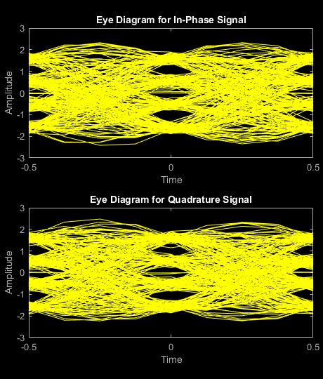
为滤波后的无噪声信号的一部分创建一个眼图,以可视化脉冲整形的效果。发射信号具有 RRC 滤波,并显示 ISI(表现为眼图张开度变窄)。
eyediagram(txFiltSignal(1:2000),sps*2);

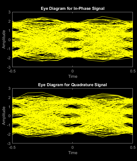
在信号经过信道噪声后,信号眼图显示 RRC 滤波和噪声对该信号的影响。噪声电平导致眼图眼张开度进一步变窄。
eyediagram(rxSignal(1:2000),sps*2);

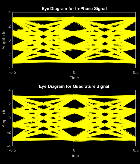
在对信号应用接收滤波后,信号眼图显示升余弦滤波对该信号的影响。与具有 RRC 滤波的信号相比,眼图眼张开度越宽,具有升余弦滤波的信号的 ISI 越少。
eyediagram(rxFiltSignal(1:2000),2);

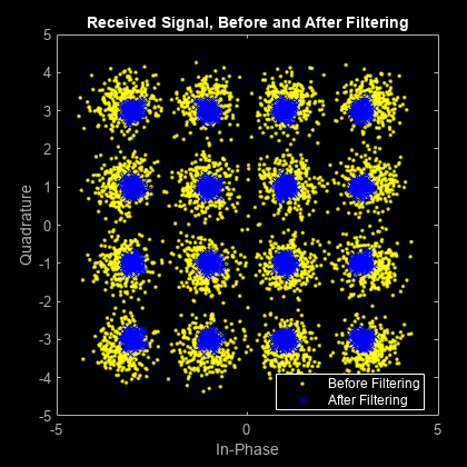
创建一个滤波前后接收信号的星座图。按每符号采样数的平方根缩放接收信号,以归一化发射和接收功率电平。
scatplot = scatterplot(sqrt(sps)*...
    rxSignal(1:sps*5e3),...
    sps,0);
hold on;
scatterplot(rxFiltSignal(1:5e3),1,0,'bx',scatplot);
title('Received Signal, Before and After Filtering');
legend('Before Filtering','After Filtering');
axis([-5 5 -5 5]); % Set axis ranges
hold off;
