Choose an Interface for an IP Core
You can generate an IP core for a design under test (DUT) and interface the generated IP core to the rest of your system by using AXI4, AXI4-Lite, AXI4 Master, AXI4-stream, AXI4-Stream Video, internal or external I/O, or FPGA data capture interfaces. The image shows how the interfaces connect the processor to the DUT:
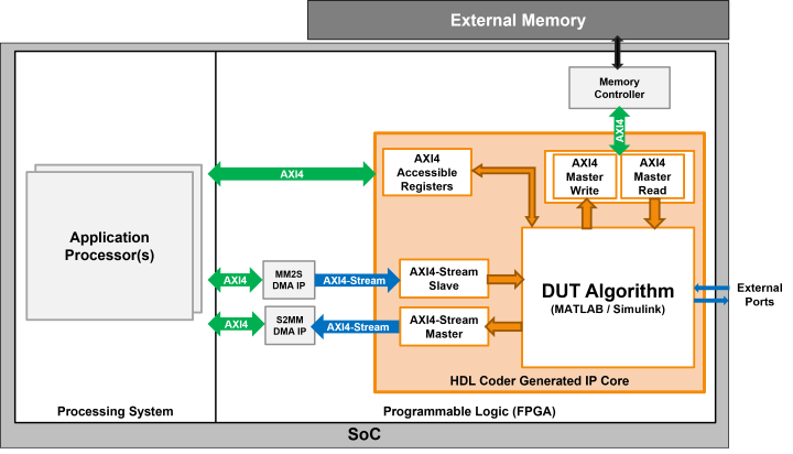
To determine the most appropriate interface, consider the intended use, supported data types, required tools, and the associated strengths and limitations of each interface.
Supported Interface Methods
This table summarizes the key aspects of the different available interfaces, target use cases, supported data types, and interface limitations.
| Interface Type | Use Cases | Data Types | Strengths | Limitations |
| Register Interface (AXI4-Lite/AXI4) | Use this interface to access the control and status registers in your design. You can choose between AXI4-Lite or AXI4 protocol for the register interface. Use AXI4-Lite if you need only lightweight data transfers. Use AXI4 to connect to components that support burst data transfers. | Supported data types:
Unsupported data types:
| AXI4-Lite
|
|
| AXI4 Master | Use this interface for designs that require you to access memory, or to control other IP cores with AXI4 or AXI4-Lite interfaces. Example applications include moving large amounts of data between your algorithm and external DDR memory. | Supported data types:
Unsupported data types:
|
| When you use the AXI4 Master interface, you must:
|
| AXI4-Stream | Use this interface for moving streaming data or transferring data at high speeds. Example applications include:
You can model your algorithm to operate on a stream of samples or on frames. | Supported data types:
Supported for sample-based modeling:
Supported for frame-based modeling:
Unsupported data types:
|
| When using the AXI4-Stream interface, you must:
|
| AXI4-Stream Video | Use this interface for video streaming applications. You can model the algorithm to operate on a stream of samples or on frames. | Supported data types:
For frame-based modeling, matrices are supported.(Since R2023a). Unsupported data types:
|
| When using the AXI4-Stream Video interface, you must:
When you choose your algorithm to operate on frames, you cannot use the MATLAB-to-HDL workflow. |
| Internal I/O | Use this interface to connect directly to other IP cores in the reference design. | Supported data types:
Unsupported data types:
| Modeling is less complex and the code generator does not generate additional protocol logic. |
|
| External I/O and External Port | Use this interface to connect to peripherals on your hardware board, such as LEDs, push buttons, DIP switches, FPGA pins, and so on. | Supported data types:
Unsupported data types:
|
|
|
| FPGA Data Capture | Use this interface to capture raw data from outputs or signals by using test points in your design and then use the data to debug your design. | Supported data types:
Unsupported data types:
|
|
|
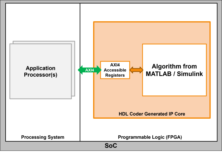
Register Interface (AXI4-Lite/AXI4)
Use this interface to access control and status registers in your design. You can choose between the AXI4-Lite or AXI4 protocols. Use AXI4-Lite if you need only lightweight data transfers. Use AXI4 to connect to components that support burst data transfers.
| Interface Name | Considerations |
| AXI4-Lite | Limited bandwidth. Not suitable for high-throughput data transfers. |
| AXI4 | Higher hardware resource consumption. |
For additional information, see:
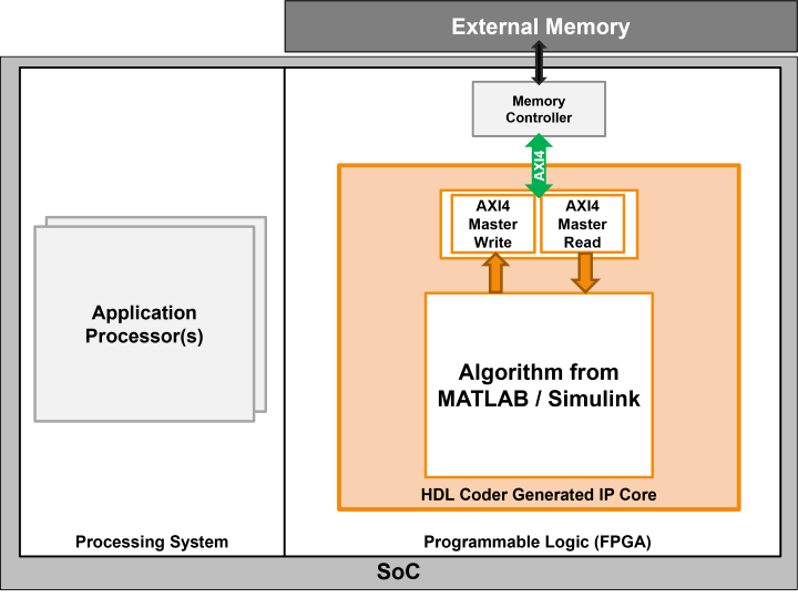
AXI4 Master
Use the AXI4 Master interface for designs that require you to access memory or control other IP cores with AXI4 or AXI4-Lite interfaces. For example, you can use this interface to move large amounts of data between your algorithm and external DDR memory.
| Interface Name | Considerations |
| AXI4 Master | This interface has a more complex implementation and requires more resources compared to the AXI4-Stream interface. |
For more information, see:
AXI4-Stream and AXI4-Stream Video
Use the AXI4-Stream interface to move streaming data or transfer data at high speeds. Example applications include:
Connecting to analog/digital converters (ADCs/DACs)
Connecting to video pipelines
Transferring large amounts of data between processors and FPGA by using DMA
You can model the algorithm to operate on a stream of samples or on frames. You can model your algorithm to operate on a stream of samples or on frames.
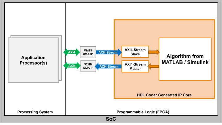
For example, this image shows how you can use an AXI4-Stream interface between multiple IP cores.

| Interface Name | Considerations |
| AXI4-Stream |
|
| AXI4-Stream Video |
|
For additional information, see:
Internal I/O
Use the internal I/O interface to connect directly to other IP cores in the reference design. The internal I/O interface is defined by the reference design. When you map to an internal I/O interface, HDL Coder™ connects the other IP cores with a wire.
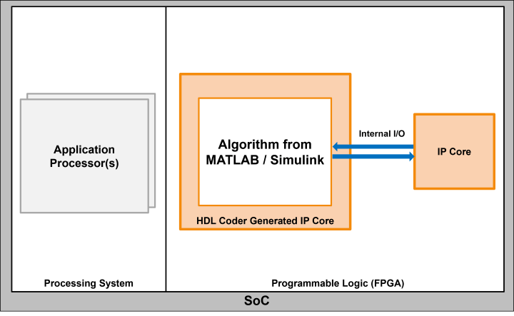
| Interface Name | Challenges |
| Internal I/O | Since there is no established protocol you have to consider additional factors such as supported port widths, synthesis tool specific naming formats, and so on, when integrating multiple components together. |
For additional information, see addInternalIOInterface.
External I/O and External Port
Use this interface to connect to peripherals on your hardware board, such as LEDs, push buttons, DIP switches, FPGA pins, and so on.
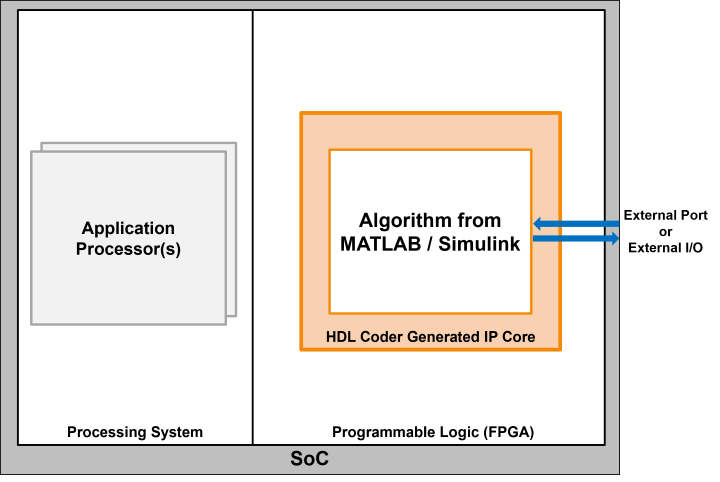
| Interface Name | Considerations |
| External I/O |
|
For additional information, see:
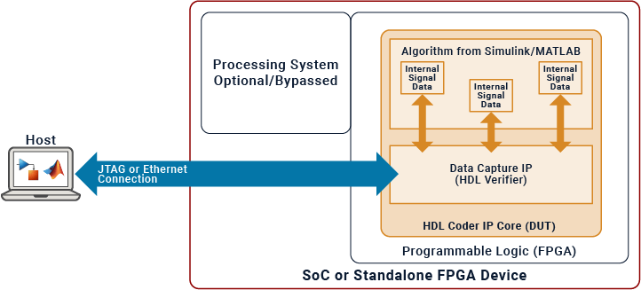
FPGA Data Capture
To interface with internal signals in your IP core, use an FPGA data capture. When you develop a model using Simulink®, you can automatically integrate this method with the IP core. This method usually involves establishing a JTAG connection to the host. You can employ test points to monitor the internal signals of the IP core while your hardware-software design runs on the hardware. FPGA data capture is useful when debugging and analyzing the design of the IP core because it eliminates the need for interface protocol modeling.
You can use FPGA data capture in the Run and Verify IP Core on Target Hardware stage of the hardware-software co-design process.
| Interface Name | Consideration |
|---|---|
| FPGA Data Capture |
|
For additional information, see Debug IP Core Using FPGA Data Capture.