Deploy Simscape Grid Tied Converter Model to Speedgoat IO Module Using HDL Workflow Script
This example shows how to deploy a three-phase two-level voltage source converter connected to a low voltage grid modeled in Simscape™ to a Speedgoat® IO334 Simulink®-programmable I/O module to achieve a simulation time step of 1 microsecond (us).
The PWM signals can be captured with an increased resolution by modeling the converter using the subcycle averaging method. A maximum resolution of 4ns is possible, allowing to simulate state of the art power converters with switching frequencies above 100kHz. The switching frequency of this example is 20kHz.
This example demonstrates how to:
Convert your Simscape model into an HDL-compatible implementation model by using the Simscape HDL Workflow Advisor
Generate HDL code and
FPGAbitstream for the IO334 module by using the HDL Workflow Advisor.Deploy the real-time model to the Speedgoat real-time target machine by using Simulink Real-Time™.
The plant model runs eventually at a 1us time step on the FPGA and the controller is executed at a 50us time step on the CPU of the real-time system. To generate HDL code and FPGA bitstream, this example shows how to run the HDL workflow script from the command line. You can use the Workflow Advisor User Interface to run this workflow. For more information, see FPGA-Based HIL Deployment of Simscape Model on Speedgoat FPGA I/O Module.
Setup and Configuration
Before deploying your algorithm on the Speedgoat IO module:
1. To synthesize the generated HDL code, before you use HDL Coder™ to generate code, set up your synthesis tool path. For example, if your synthesis tool is Xilinx® Vivado®, install the latest version of Xilinx Vivado as shown in HDL Language Support and Supported Third-Party Tools and Hardware.
Then, set the tool path to the installed Xilinx Vivado executable by using the hdlsetuptoolpath function. For example, this command sets the synthesis tool path to point to your installed Vivado® Design Suite 2024.1 batch file:
hdlsetuptoolpath("ToolName","Xilinx Vivado",...
"ToolPath","C:\Xilinx\Vivado\2024.1\bin\vivado.bat")
2. For real-time simulation, set up the development environment and target computer settings. See Get Started with Simulink Real-Time (Simulink Real-Time).
3. To install your Speedgoat I/O Blockset and the Speedgoat - HDL Coder Integration packages, go to www.speedgoat.com/extranet, the Speedgoat® Customer Portal. Follow the instructions to download and install the Speedgoat I/O Blockset.
Three-Phase Two-Level Voltage Source Converter Model
To see the three-phase two-level converter model, run this command:
open_system('sschdlexThreePhaseConverterWithGridExample')
This example model consists of a three-phase two-level voltage source converter connected to a low voltage grid through an LC filter. A circuit breaker allows to disconnect and connect the converter with the grid. There is a low voltage load on the grid side and a transformer connecting to the medium voltage grid.
In the first step, the model is used to validate the closed-loop control by desktop simulation. The controller consists of a phase-locked loop for grid synchronization and PI current control in the synchronous reference frame.
In a second step, the model can be deployed to the real-time platform for HIL testing of the embedded controller.
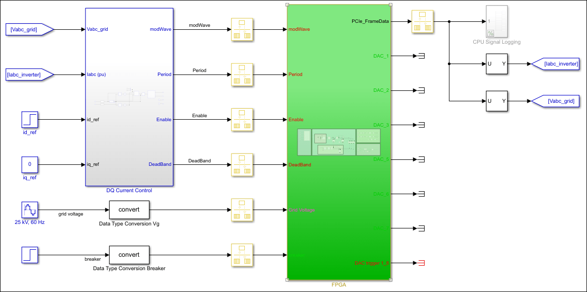
The model has been partitioned into parts that run on the FPGA and parts that run on the CPU in real time. Parts inside the green FPGA subsystem run on the FPGA. Parts outside this subsystem run on the CPU in real time.
open_system('sschdlexThreePhaseConverterWithGridExample/FPGA')

Run Desktop Simulation of Simscape Model
The base sample rate is set to 1/(180e6) to match the clock ticks at the target frequency of 180 MHz on the hardware. To accelerate the desktop simulation, you can consider increasing the value of base sample rate.
Tbase = 1/(180e6);
Set the simulation and step time to close the circuit breaker
set_param('sschdlexThreePhaseConverterWithGridExample','StopTime','0.09');
set_param(['sschdlexThreePhaseConverterWithGridExample','/Step'],'Time','0.03');
Desktop simulation of the model
sim('sschdlexThreePhaseConverterWithGridExample')
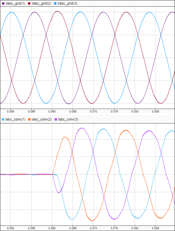
Display output signals of three-phase two-level voltage source converter in Simulink Data Inspector
Simulink.sdi.clearAllSubPlots
Simulink.sdi.setSubPlotLayout(2,1);
allIDs = Simulink.sdi.getAllRunIDs;
runID1 = allIDs(end);
run1 = Simulink.sdi.getRun(runID1);
run1.name = 'Desktop Simulation';
Vabc_grid = run1.getSignalsByName('Vabc_grid');
Iabc_conv = run1.getSignalsByName('Iabc_conv');
plotOnSubPlot(Vabc_grid.Children(1),1,1,true);
plotOnSubPlot(Vabc_grid.Children(2),1,1,true);
plotOnSubPlot(Vabc_grid.Children(3),1,1,true);
plotOnSubPlot(Iabc_conv.Children(1),2,1,true);
plotOnSubPlot(Iabc_conv.Children(2),2,1,true);
plotOnSubPlot(Iabc_conv.Children(3),2,1,true);
Simulink.sdi.view;

Generate HDL Implementation Model
For HDL code generation compatibility, you run the Simscape HDL Workflow Advisor to generate an HDL implementation model.
The Simscape solver is set to run for one iteration at each sample step. The Simscape HDL Workflow Advisor uses the solver settings in the next step for deterministic real-time behavior.
The averaged switch model allows us to set the solver iterations to 1
set_param(['sschdlexThreePhaseConverterWithGridExample','/FPGA/Solver Configuration'],'DoFixedCost','on')
set_param(['sschdlexThreePhaseConverterWithGridExample','/FPGA/Solver Configuration'],'MaxNonlinIter','1')
To accelerate the sschdladvisor we reduce the sample time of the model. The time at which the circuit breaker closes is adapted to make sure that the workflow advisor captures all switching modes during simulation.
set_param('sschdlexThreePhaseConverterWithGridExample','StopTime','0.002');
set_param(['sschdlexThreePhaseConverterWithGridExample','/Step'],'Time','0.001');
To open the Advisor, run the sschdladvisor function for your model:
sschdladvisor('sschdlexThreePhaseConverterWithGridExample')
To generate the implementation model, in the Simscape HDL Workflow Advisor, keep the default settings for the tasks, and then run the tasks. Run the tasks in the Advisor by clicking the Run all button. You see a link to the generated model in the Generate implementation model task. This model has the same name as your original model with the prefix gmStateSpaceHDL_.
We set the simulation and step time to the original values
set_param('sschdlexThreePhaseConverterWithGridExample','StopTime','0.09');
set_param(['sschdlexThreePhaseConverterWithGridExample','/Step'],'Time','0.03');
Prepare Implementation Model for HDL Code Generation
To open the implementation model, click the link in the Generate implementation model task.
open_system('gmStateSpaceHDL_sschdlexThreePhaseConverter')

set_param('gmStateSpaceHDL_sschdlexThreePhaseConverter','StopTime','0.09');
set_param(['gmStateSpaceHDL_sschdlexThreePhaseConverter','/Step'],'Time','0.03');
The model contains a switched linear Simulink replacement of the original three-phase two-level voltage source converter model. You see that the Simscape model was replaced.
open_system('gmStateSpaceHDL_sschdlexThreePhaseConverter/FPGA')
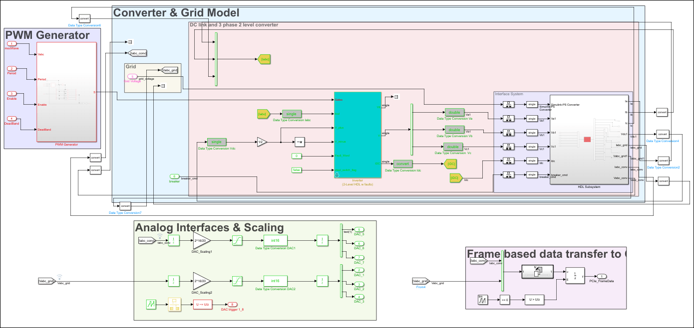
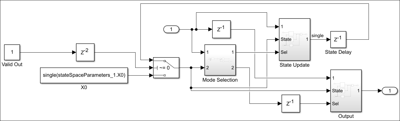
The implementation model replaces the Simscape subsystem with the HDL-compatible algorithm that performs the state-space computations. When you navigate inside this subsystem, you see several delays, adders, and Matrix Multiply blocks that model the state-space equations. From and Goto blocks inside this subsystem provide the same input as that of the original model to the HDL Subsystem.
open_system('gmStateSpaceHDL_sschdlexThreePhaseConverter/FPGA/HDL Subsystem/HDL Algorithm')
Run Desktop Simulation of HDL Implementation Model and Validate HDL Algorithm
You can simulate the switched linear state-space model of the three-phase two-level voltage source converter in Simulink and display the signals in Simulation Data Inspector. The comparison of the runs show that the numeric results match with the original Simscape model.
Simulate the HDL implementation model.
sim('gmStateSpaceHDL_sschdlexThreePhaseConverter')
Display output signals of three-phase two-level voltage source converter Simscape model in Simulink Data Inspector
Simulink.sdi.clearAllSubPlots
Simulink.sdi.setSubPlotLayout(2,1);
allIDs = Simulink.sdi.getAllRunIDs;
runID1 = allIDs(end);
run2 = Simulink.sdi.getRun(runID1);
run2.name = 'HDL Model Simulation';
Vabc_grid = run2.getSignalsByName('Vabc_grid');
Iabc_conv = run2.getSignalsByName('Iabc_conv');
plotOnSubPlot(Vabc_grid.Children(1),1,1,true);
plotOnSubPlot(Vabc_grid.Children(2),1,1,true);
plotOnSubPlot(Vabc_grid.Children(3),1,1,true);
plotOnSubPlot(Iabc_conv.Children(1),2,1,true);
plotOnSubPlot(Iabc_conv.Children(2),2,1,true);
plotOnSubPlot(Iabc_conv.Children(3),2,1,true);
Simulink.sdi.view;
To verify that the HDL implementation model matches the original Simscape model, generate a state-space validation model. In the Generate implementation model task, select the Generate validation logic for the implementation model check box and then run this task. Simulating the model does not display assertions, which indicates that the numeric results match. See Validate HDL Implementation Model to Simscape Algorithm.
HDL Workflow Advisor
The HDL Workflow Advisor guides you through HDL code generation and the FPGA design process. Use the Advisor to:
Check the model for HDL code generation compatibility and fix incompatible settings.
Generate HDL code, test bench, and scripts to build and run the code and test bench.
Perform synthesis, timing analysis, and deploy the generated code on SoCs, FPGAs, and Speedgoat I/O modules.
You run the Advisor for the FPGA subsystem in your model. To open the HDL Workflow Advisor for the subsystem inside the model, use the hdladvisor function. For example:
hdladvisor('gmStateSpaceHDL_sschdlexThreePhaseConverter/FPGA')
To learn about the tasks in the Advisor, right-click that task, and select What's This?. See Getting Started with the HDL Workflow Advisor.
Run Workflow Script to Generate Simulink Real-Time Interface Model
You can export the HDL Workflow Advisor settings to a script to expedite and automate your workflow. The script is a MATLAB® file that you run from the command line. You can modify and run the script, or import the settings into the HDL Workflow Advisor User Interface. See Run HDL Workflow with a Script.
This example shows how to run the HDL Workflow script. To generate a Simulink Real-Time Interface model, open and run this MATLAB script.
edit('hdlworkflow_IO334')
%% ------------------------------------------------------------------------
% This script contains the model, target settings, interface mapping, and
% the Workflow Configuration settings for generating HDL code for the HDL
% implementation model generated for the three-phase two-level voltage source
% converter model, and for deploying the code to the FPGA on board the
% Speedgoat IO334-325K module.
%% -----------------------------------------------------------------------

% Make the model ready for HDL code generation

% Set all data type conversion blocks to type single (except the
% conversions for the analog output signals.
DataTypeConversionBlocks = Simulink.findBlocksOfType([HDLModelName,'/FPGA'],'DataTypeConversion',Simulink.FindOptions('SearchDepth',1));
for i = 1:length(DataTypeConversionBlocks)
    BlockName = get_param(DataTypeConversionBlocks(i),'Name');
    if ~any(strcmp(BlockName,{'Data Type Conversion DAC1','Data Type Conversion DAC2'}))
        set_param([HDLModelName,'/FPGA/',BlockName],'OutDataTypeStr','single');
    end
end

set_param([HDLModelName,'/Data Type Conversion Vg'],'OutDataTypeStr','single');
set_param([HDLModelName,'/Data Type Conversion Breaker'],'OutDataTypeStr','single');

% Set the base sample time to 1/(180e6) (equal to a clock tick at 180MHz target
% frequency). Note: The base rate determines the resolution of the PWM
% signal when running the model on hardware.
Tbase = 1/180e6;

% Model HDL parameters
% -------------------------------------------------------------------------

% Set the model HDL parameters
hdlset_param(HDLModelName, 'FloatingPointTargetConfiguration', hdlcoder.createFloatingPointTargetConfig('NativeFloatingPoint', 'LatencyStrategy', 'MAX'));
hdlset_param(HDLModelName, 'HDLSubsystem', [HDLModelName,'/FPGA']);
hdlset_param(HDLModelName, 'Oversampling',1);
hdlset_param(HDLModelName, 'ScalarizePorts', 'DUTLevel');
hdlset_param(HDLModelName, 'TargetFrequency', 180);
hdlset_param(HDLModelName, 'Workflow', 'Simulink Real-Time FPGA I/O');
hdlset_param(HDLModelName, 'TargetPlatform', 'Speedgoat IO334-325k');
hdlset_param(HDLModelName, 'TargetDirectory', 'c:\hdl_prj\hdlsrc');
hdlset_param(HDLModelName,'ResetType','Synchronous')
hdlset_param(HDLModelName, 'AdaptivePipelining', 'on');
hdlset_param(HDLModelName, 'ReferenceDesignParameter', {'PCIe_Link_Width','X4','RearPlugin','None','AuroraMode','None','AuroraByteswap','true'});

% Block ram options
hdlset_param([HDLModelName,'/FPGA/HDL Subsystem/HDL Algorithm/State Update/Multiply Input'], 'UseRAM', 'on');
hdlset_param([HDLModelName,'/FPGA/HDL Subsystem/HDL Algorithm/State Update/Multiply State'], 'UseRAM', 'on');

% Set input and output pipeline registers
hdlset_param([HDLModelName,'/FPGA/HDL Subsystem/HDL Algorithm'], 'ConstrainedOutputPipeline', 2);
hdlset_param([HDLModelName,'/FPGA/HDL Subsystem/HDL Algorithm'], 'InputPipeline', 2);
hdlset_param([HDLModelName,'/FPGA/HDL Subsystem/HDL Algorithm'], 'OutputPipeline', 2);

hdlset_param([HDLModelName,'/FPGA/HDL Subsystem/HDL Algorithm/Mode Selection'], 'ConstrainedOutputPipeline', 2);
hdlset_param([HDLModelName,'/FPGA/HDL Subsystem/HDL Algorithm/Mode Selection'], 'OutputPipeline', 2);

hdlset_param([HDLModelName,'/FPGA/HDL Subsystem/HDL Algorithm/Output'], 'ConstrainedOutputPipeline', 2);
hdlset_param([HDLModelName,'/FPGA/HDL Subsystem/HDL Algorithm/Output'], 'OutputPipeline', 2);

hdlset_param([HDLModelName,'/FPGA/HDL Subsystem/HDL Algorithm/State Update'], 'ConstrainedOutputPipeline', 2);
hdlset_param([HDLModelName,'/FPGA/HDL Subsystem/HDL Algorithm/State Update'], 'OutputPipeline', 2);

% Enable flatten hyrarchy
hdlset_param([HDLModelName,'/FPGA'], 'FlattenHierarchy', 'on');

% Set the code generation options for the MATLAB function to "data path"
hdlset_param([HDLModelName,'/FPGA/HDL Subsystem/HDL Algorithm/Mode Selection/Generate Mode Vector'], 'Architecture', 'MATLAB Datapath');

% We define the hardware interfaces for all input and output ports to the
% FPGA subsystem

% Set inport HDL parameters
hdlset_param([HDLModelName,'/FPGA/modWave'], 'IOInterface', 'PCIe Interface');
hdlset_param([HDLModelName,'/FPGA/modWave'], 'IOInterfaceMapping', 'x"100"');

hdlset_param([HDLModelName,'/FPGA/Period'], 'IOInterface', 'PCIe Interface');
hdlset_param([HDLModelName,'/FPGA/Period'], 'IOInterfaceMapping', 'x"114"');

hdlset_param([HDLModelName,'/FPGA/Enable'], 'IOInterface', 'PCIe Interface');
hdlset_param([HDLModelName,'/FPGA/Enable'], 'IOInterfaceMapping', 'x"118"');

hdlset_param([HDLModelName,'/FPGA/DeadBand'], 'IOInterface', 'PCIe Interface');
hdlset_param([HDLModelName,'/FPGA/DeadBand'], 'IOInterfaceMapping', 'x"11C"');

hdlset_param([HDLModelName,'/FPGA/Grid Voltage'], 'IOInterface', 'PCIe Interface');
hdlset_param([HDLModelName,'/FPGA/Grid Voltage'], 'IOInterfaceMapping', 'x"120"');

hdlset_param([HDLModelName,'/FPGA/breaker'], 'IOInterface', 'PCIe Interface');
hdlset_param([HDLModelName,'/FPGA/breaker'], 'IOInterfaceMapping', 'x"134"');

% Set outport HDL parameters
hdlset_param([HDLModelName,'/FPGA/PCIe_FrameData'], 'IOInterface', 'PCIe Interface');
hdlset_param([HDLModelName,'/FPGA/PCIe_FrameData'], 'IOInterfaceMapping', 'x"1000"');

hdlset_param([HDLModelName,'/FPGA/DAC_1'], 'IOInterface', 'IO334 AO Data [0:15]');
hdlset_param([HDLModelName,'/FPGA/DAC_1'], 'IOInterfaceMapping', 'Channel 01');

hdlset_param([HDLModelName,'/FPGA/DAC_2'], 'IOInterface', 'IO334 AO Data [0:15]');
hdlset_param([HDLModelName,'/FPGA/DAC_2'], 'IOInterfaceMapping', 'Channel 02');

hdlset_param([HDLModelName,'/FPGA/DAC_3'], 'IOInterface', 'IO334 AO Data [0:15]');
hdlset_param([HDLModelName,'/FPGA/DAC_3'], 'IOInterfaceMapping', 'Channel 03');

hdlset_param([HDLModelName,'/FPGA/DAC_5'], 'IOInterface', 'IO334 AO Data [0:15]');
hdlset_param([HDLModelName,'/FPGA/DAC_5'], 'IOInterfaceMapping', 'Channel 05');

hdlset_param([HDLModelName,'/FPGA/DAC_6'], 'IOInterface', 'IO334 AO Data [0:15]');
hdlset_param([HDLModelName,'/FPGA/DAC_6'], 'IOInterfaceMapping', 'Channel 06');

hdlset_param([HDLModelName,'/FPGA/DAC_7'], 'IOInterface', 'IO334 AO Data [0:15]');
hdlset_param([HDLModelName,'/FPGA/DAC_7'], 'IOInterfaceMapping', 'Channel 07');

hdlset_param([HDLModelName,'/FPGA/DAC trigger 1_8'], 'IOInterface', 'IO334 AO Trigger [0:1]');
hdlset_param([HDLModelName,'/FPGA/DAC trigger 1_8'], 'IOInterfaceMapping', 'Channel 01 to 08');

%% Workflow Configuration Settings

% Construct the Workflow Configuration Object with default settings
hWC = hdlcoder.WorkflowConfig('SynthesisTool','Xilinx Vivado','TargetWorkflow','Simulink Real-Time FPGA I/O');

% Specify the top level project directory (make sure to define a short
% specific path)
hWC.ProjectFolder = 'c:/hdl_prj';
hWC.IgnoreToolVersionMismatch = true;

% Set properties related to 'RunTaskCreateProject' Task
hWC.Objective = hdlcoder.Objective.SpeedOptimized;

% Set Workflow tasks to run
hWC.RunTaskGenerateRTLCodeAndIPCore = true;
hWC.RunTaskCreateProject = true;
hWC.RunTaskBuildFPGABitstream = true;
hWC.RunTaskGenerateSimulinkRealTimeInterface = true;

%% Run the workflow
hdlcoder.runWorkflow([HDLModelName,'/FPGA'], hWC);

%% Get the model ready for deployment on the Speedgoat real-time target machine

% Get the name of the generate real-time model
SLRTModelName = ['gm_',HDLModelName,'_slrt'];

% Comment through all rate transition blocks. The entire CPU model runs at
% a time step of 50us. The rate transitions between the FPGA and CPU model
% happen implicitly through the CPU read and write operations.
RateTransitionBlocks = Simulink.findBlocksOfType(SLRTModelName,'RateTransition',Simulink.FindOptions('SearchDepth',1));
for i = 1:length(RateTransitionBlocks)
    BlockName = get_param(RateTransitionBlocks(i),'Name');
    if ~any(strcmp(BlockName,{'Data Type Conversion DAC1','Data Type Conversion DAC2'}))
        set_param([SLRTModelName,'/',BlockName],'Commented','through');
    end
end

% Uncomment the subsystem for data logging on the real-time CPU
set_param([SLRTModelName,'/CPU Signal Logging'],'Commented','off');
Prepare Simulink Real-Time Interface Model for Real-Time Simulation
Running the workflow script generates RTL code and IP core, creates a Vivado project, builds the FPGA bitstream, and then generates the Simulink Real-Time Interface model.

Before deploying the model to the Speedgoat real-time target machine, getting model ready for real time testing:
generated_model = get_param(gcs,'Name');
% comment through all rate transition blocks
RateTransitionBlocks = Simulink.findBlocksOfType(generated_model,'RateTransition',Simulink.FindOptions('SearchDepth',1));
for i = 1:length(RateTransitionBlocks)
    BlockName = get_param(RateTransitionBlocks(i),'Name');
    if ~any(strcmp(BlockName,{'Data Type Conversion DAC1','Data Type Conversion DAC2'}))
        set_param([generated_model,'/',BlockName],'Commented','through');
    end
end
% uncomment the subsystem for logging
set_param([generated_model,'/CPU Signal Logging'],'Commented','off');
Connect to Target Machine and Run Real-Time Simulation
The model can now be deployed to the Speedgoat real-time target machine. The three-phase two-level voltage source converter model is automatically loaded to the FPGA on the IO334.
Connect to the Speedgoat real-time target machine.
tg = slrealtime;
connect(tg);
Build and download the model to the target machine.
model = 'generated_model';
open_system(model);
modelSTF = getSTFName(tg);
set_param(model,"SystemTargetFile",modelSTF)
set_param(model,'FixedStep','.01');
evalc('slbuild(model)');
Start the model execution.
load(tg,model);
start(tg);
while strcmp(tg.status,'running')
    pause(10);
end
The file logging blocks store the signals on the SSD of the target-machine. The data is automatically uploaded to the host computer once the model is stopped. The data is visualized in Simulation Data Inspector. You can verify that the results of the real-time simulation matches the original Simscape model.
% Display grid voltage and converter current in SDI
Simulink.sdi.clearAllSubPlots
Simulink.sdi.setSubPlotLayout(2,1);
allIDs = Simulink.sdi.getAllRunIDs;
runID1 = allIDs(end);
run3 = Simulink.sdi.getRun(runID1);
run3.name = 'Real-Time Simulation';
Vabc_grid = run3.getSignalsByName('Vabc_grid');
Iabc_conv = run3.getSignalsByName('Iabc_conv');
plotOnSubPlot(Vabc_grid.Children(1),1,1,true);
plotOnSubPlot(Vabc_grid.Children(2),1,1,true);
plotOnSubPlot(Vabc_grid.Children(3),1,1,true);
plotOnSubPlot(Iabc_conv.Children(1),2,1,true);
plotOnSubPlot(Iabc_conv.Children(2),2,1,true);
plotOnSubPlot(Iabc_conv.Children(3),2,1,true);
Simulink.sdi.view;
Alternatively, you can measure the signals at the analog output of the IO334.