Generate HDL IP Core with Multiple AXI4-Stream and AXI4 Master Interfaces
When you run the generic IP Core Generation workflow for your Simulink® model or target your own custom reference design that you authored, you can generate an HDL IP core with multiple AXI4-Stream interfaces, AXI4-Stream Video interfaces, or AXI4 Master interfaces. To learn about these interfaces, see Target Platform Interfaces.
Why Use Multiple AXI4 Interfaces
You can use multiple streaming interfaces to facilitate high-speed data transfer in various applications such as:
Transferring data between A/D and D/A converters
Software-defined radio algorithms that process multiple transceiver channels
Vision algorithms that perform image annotation or object detection
Specify Multiple AXI4 Interfaces in Generic IP Core Generation Workflow
To specify more than one AXI4-Stream, AXI4-Stream Video, or AXI4 Master channel:
In the Set Target Device and Synthesis Tool task, select
IP Core Generationas the Target workflow andGeneric Xilinx PlatformorGeneric Altera Platformas the Target platform. Run this task.To add multiple target interfaces, in the Set Target Interface task, on the Target Platform Interfaces section of the Target platform interface table, select Add more ....

You can then add more interfaces in the Add New Target Interfaces dialog box. Specify the type of interface you want to add, the number of interfaces, and a custom name for each additional interface.
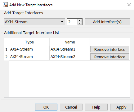
After you apply the settings, the interfaces you created appear in the Target platform interface table. After you run this task, the additional interfaces specified are saved on the DUT subsystem as the HDL block property AdditionalTargetInterfaces.
If you modify the additional interfaces that were already mapped to DUT ports such
as deleting or renaming an interface that was already mapped, the previous interface
mapping information might be lost. The ports then become unmapped to interfaces and
the Target platform interfaces section displays No
interface specified. Therefore, if you make changes to the
additional target interfaces, verify that the DUT ports are mapped to the
correct target interfaces.
Specify Multiple AXI4 Interfaces in Custom Reference Designs
When you create your own custom reference design, you can add multiple
AXI4-Stream, AXI4-Stream Video, and AXI4 Master
interfaces. Depending on the interface type you want to add, specify additional
interfaces by using the addAXI4StreamInterface,
addAXI4StreamVideoInterface, or
addAXI4MasterInterface methods of
the hdlcoder.ReferenceDesign
class.
To add more interfaces, in the plugin_rd file, call the
interface method each time you want to add more interfaces. This example shows how
to add two AXI4-Stream interfaces.
function hRD = plugin_rd()
% Reference design definition

%   Copyright 2017-2019 The MathWorks, Inc.

% Construct reference design object
hRD = hdlcoder.ReferenceDesign('SynthesisTool', 'Xilinx Vivado');

hRD.ReferenceDesignName = 'Multiple Interface Reference Design';
hRD.BoardName = 'ZedBoard';

% Tool information
hRD.SupportedToolVersion = {'2019.1'};

% ...
% ...

% Add AXI4-Stream interface 1
hRD.addAXI4StreamInterface (...
    'MasterChannelEnable',      true, ...
    'SlaveChannelEnable',       true, ...
    'MasterChannelConnection',  'axi_dma_s2mm/S_AXIS_S2MM', ...
    'SlaveChannelConnection',   'axi_dma_mm2s/M_AXIS_MM2S', ...
    'MasterChannelDataWidth',   32, ...
    'SlaveChannelDataWidth',    32, ...
    'InterfaceID',              'AXI4-Stream1');

% Add AXI4-Stream interface 2
hRD.addAXI4StreamInterface (...
    'MasterChannelEnable',      true, ...
    'SlaveChannelEnable',       true, ...
    'MasterChannelConnection',  'ADC/S_AXIS_S2MM', ...
    'SlaveChannelConnection',   'DAC/M_AXIS_MM2S', ...
    'MasterChannelDataWidth',   32, ...
    'SlaveChannelDataWidth',    32, ...
    'InterfaceID',              'AXI4-Stream2');


% ...
% ...
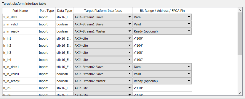
When you run the IP Core Generation workflow and target the
custom reference design Multiple Interface Reference Design, in
the Set Target Interface task, you can map the DUT ports to
AXI4-Stream1 Master and
Slave channels and AXI4-Stream2
Master and Slave
channels.
Note
When you target your own custom reference design and map the additional
interfaces to DUT ports in the Set Target Interfaces task,
the additional interfaces are not saved on the model as the
AdditionalTargetInterfaces HDL block property. Instead,
the additional interfaces are saved on the custom reference design in the
plugin_rd.m file.
You can also dynamically customize the reference design to specify the number of interfaces you want to add and the interface properties.
In the
plugin_rdfile, create a reference design parameter for the number of additional interfaces you want to add.Create a callback function that has different choices for the number of interfaces you want to add and then reference the function in the
plugin_rdfile by using theCustomizeReferenceDesignFcnmethod of thehdlcoder.ReferenceDesignclass.
To learn more, see Customize Reference Design Dynamically Based on Reference Design Parameters.
Ready Signal Mapping for Multiple Streaming Interfaces
When you use a single streaming channel, HDL Coder™ automatically generates the Ready signal and the associated back pressure logic.
If you use multiple streaming channels, HDL Coder does not automatically generate the back pressure logic. In this case, the Ready signal is generated but the master Ready signal at the input is ignored and the slave Ready signal at the output is tied to high value. The absence of a back pressure logic can result in samples being dropped. If you want your design to apply back pressure on the Slave interface or respond to back pressure from the Master interface, you must model the Ready signal for each additional interface and then map the port to the Ready signal for that interface. When you do not model, the Set Target Interface task displays a warning that provides names of interfaces that require a Ready port. If your design does not need to apply or respond to back pressure, you can ignore this warning and you do not have to model the Ready signal.
When using multiple AXI4-Stream interfaces, if you want your design to apply back pressure on the Slave interface or respond to back pressure from the Master interface, you must model the Ready signal for each additional interface and then map the port to the Ready signal for that interface. To learn how the back pressure logic is generated for a single streaming channel and how to model the Ready signal, see Ready Signal (Optional).
Restrictions
When you run the generic IP Core Generation workflow, you can specify the interface type and a custom interface ID for each additional interface. Other interface properties such as the data width cannot be customized and use default values. When you create your own custom reference design, you can customize the interface name and interface properties.
Processor/FPGA synchronization must be
Free running.
See Also
Topics
- Hardware-Software Co-Design Workflow for SoC Platforms
- Generate Board-Independent HDL IP Core from Simulink Model