lensDistortion
Description
Add-On Required: This feature requires the Optical Design and Simulation Library for Image Processing Toolbox add-on.
computes the geometric lens distortion for the optical system ld = lensDistortion(opsys)opsys
using the lens distortion model.
Note
This functionality requires Optical Design and Simulation Library for Image Processing Toolbox™. You can install the Optical Design and Simulation Library for Image Processing Toolbox from Add-On Explorer. For more information about installing add-ons, see Get and Manage Add-Ons.
specifies options for computing the lens distortion using one or more name-value
arguments. For example, ld = lensDistortion(opsys,Name=Value)NumSamples=200 specifies to compute the lens
distortion at 200 evenly spaced coordinate points.
Examples
Create an optical system containing a camera lens by using the createDoubleGauss helper function, attached to this example as a supporting file.
opsys = createDoubleGauss;
Specify the position of the light source located at infinity in the *yz-*plane at 15 degrees below the optical axis using the FieldPoints property of the opticalSystem object.
opsys.FieldPoints = fieldPoint(Angles=[15 0]);
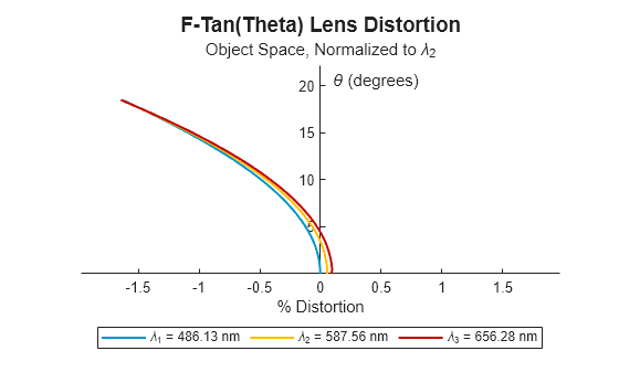
Compute the lens distortion of the optical system using the lensDistortion object function. Display the lens distortion chart using the show object function.
ld = lensDistortion(opsys); plot_ld = show(ld)

plot_ld =
LensDistortionChart with properties:
LensDistortion: [1×1 optics.result.LensDistortion]
Color: [3×3 double]
Title: "F-Tan(Theta) Lens Distortion"
Subtitle: "Object Space, Normalized to \lambda_2"
Legend: on
Grid: "off"
Parent: [1×1 Figure]
Show all properties
Input Arguments
Optical system for which to compute the lens distortion, specified as an opticalSystem object.
Name-Value Arguments
Specify optional pairs of arguments as
Name1=Value1,...,NameN=ValueN, where Name is
the argument name and Value is the corresponding value.
Name-value arguments must appear after other arguments, but the order of the
pairs does not matter.
Example: lensDistortion(NumSamples=200) specifies to compute the lens
distortion at 200 evenly spaced coordinate points.
Type of lens distortion to compute, specified as one of these options.
"FTanTheta"— The image height is proportional to the tangent of the angle of the incoming light ray with respect to the optical axis. Use this model to approximate the lens distortion of real lenses, especially wide-angle lenses, when projecting images. The radial distance r from the image center is given bywhere f is the focal length and is the angle of the incoming light ray with respect to the optical axis.
"FTheta"— The image height is directly proportional to the angle from the optical axis. Use this model to compute the lens distortion for fisheye lenses, to capture a wide field of view with a characteristic distortion pattern. The radial distance r from the image center is given byThe linear relationship between the angle and the radial distance leads to the distinctive fisheye effect.
Wavelengths for which to compute the lens distortion, specified as an
M-element numeric vector. M is the number of
wavelengths, and each element of the vector represents a wavelength, in nanometers. By
default, the lens distortion is computed at the wavelengths specified by the
Wavelengths property of the opticalSystem
object opsys.
Option to use a uniform paraxial scale across all wavelengths, specified as a
logical 1 (true) or 0
(false).
1(true) — Compute the paraxial scale for the reference wavelength, and use it to compute lens distortion for each wavelength.0(false) — Compute the paraxial scale, and therefore lens distortion, separately for each wavelength.
The paraxial scale is the scale factor that relates the size of the image in the paraxial approximation, or the ideal image, to the size of the actual image formed by the optical system.
Index of the reference wavelength, specified as a positive integer. The reference
wavelength is the wavelength at which to compute the paraxial scale used to compute
lens distortion at all wavelengths when SameScaleForAllWavelengths
is true.
If you specify the Wavelengths name-value argument, the
default index of the reference wavelength is M/2, rounded up to the
nearest integer. M is the number of wavelengths in
Wavelengths. If you do not specify the
Wavelengths name-value argument, the default reference
wavelength is the primary wavelength specified by the PrimaryWavelengthIndex property of the
opticalSystem object opsys.
Maximum field angle, or angle from the optical axis, at which to compute the lens
distortion, specified as a numeric scalar in the range [0, 180]. By default,
MaxFieldAngle value is 0.9 times the value of the half-angle of
the optical system opsys. To compute the half field of view, or
half-angle, use the halfFieldOfView function.
Decrease the field angle to minimize discontinuities at the possible expense of missing important performance information at larger field angles, such as vignetting.
Space in which to compute lens distortion, specified as one of these options.
"ObjectSpace"— Compute lens distortion effects from the perspective of the object being imaged. Use this option to examine how the optical system alters the perceived geometry and position of objects in the scene."ImageSpace"— Compute lens distortion effects observed in the image plane, where the sensor or film captures the image. Use this option to analyze the effect of distortion on how the final image appears.
Number of evenly sampled points at which to compute lens distortion, specified as a positive integer. To produce a smoother curve, increase the number of sampled points at the expense of increased computation time.
Distance between the object and the first surface in the optical system, specified
as a positive numeric scalar. By default, the object is located at an infinite
distance from the first surface in the optical system
opsys.
Output Arguments
Lens distortion, returned as a object.LensDistortion
More About
Distortion is the difference between the actual image position of the chief ray and its ideal, undistorted position. The chief ray is defined as a ray that originates from the field point and passes through the center of the entrance pupil halfway between the upper and lower marginal rays of the optical system. For a chief ray that is defined relative to another geometrical quantity, such as the system aperture stop, the reference points used to compute distortion can shift and alter the distortion result.
Algorithms
If you specify the ComputationSpace name-value argument as
"ObjectSpace", the lensDistortion computes the lens
distortion using these steps.
Compute the maximum field of view (FOV) of the optical system at the primary wavelength.
Sample the cone spanned from the optical axis to the maximum field angle using N equally spaced field angle values, where N is the value specified by the
NumSamplesname-value argument. ThelensDistortionfunction defines the maximum field angle as the angle specified using theMaxFieldAnglename-value argument, or as the half field of view, or half-angle, for the optical system at the reference wavelength.Compute the chief ray for each field angle to determine the actual image position.
Compute the ideal image position using the field angle and the paraxial scale values. Specify the lens distortion model to compute the ideal image position using the
Typename-value argument.Calculate the distortion, in percentage, as
where hactual is the actual computed image height, and hideal is the ideal image height computed using the paraxial focal length, or the paraxial scale, of the optical system.
If you specify the ComputationSpace name-value argument as
"ImageSpace", the lensDistortion computes the lens
distortion in these steps.
Sample the distance between the optical axis and the top of the image plane using N equally spaced image height values, where N is the value specified by the
NumSamplesname-value argument.Trace a chief ray between the image plane at the image position and the first surface in the optical system. Compute the exit angle of this chief ray.
Compute the ideal image position using the exit angle and the paraxial scale value, or paraxial focal length. Specify the lens distortion model to compute the ideal image position using the
Typename-value argument.Calculate the distortion, in percentage, as
where hactual is the actual computed image height, and hideal is the ideal image height computed using the paraxial focal length, or the paraxial scale, of the optical system.
Version History
Introduced in R2026a
MATLAB Command
You clicked a link that corresponds to this MATLAB command:
Run the command by entering it in the MATLAB Command Window. Web browsers do not support MATLAB commands.
选择网站
选择网站以获取翻译的可用内容,以及查看当地活动和优惠。根据您的位置,我们建议您选择:。
您也可以从以下列表中选择网站:
如何获得最佳网站性能
选择中国网站(中文或英文)以获得最佳网站性能。其他 MathWorks 国家/地区网站并未针对您所在位置的访问进行优化。
美洲
- América Latina (Español)
- Canada (English)
- United States (English)
欧洲
- Belgium (English)
- Denmark (English)
- Deutschland (Deutsch)
- España (Español)
- Finland (English)
- France (Français)
- Ireland (English)
- Italia (Italiano)
- Luxembourg (English)
- Netherlands (English)
- Norway (English)
- Österreich (Deutsch)
- Portugal (English)
- Sweden (English)
- Switzerland
- United Kingdom (English)