phased.WidebandLOSChannel
Wideband LOS propagation channel
Description
The phased.WidebandLOSChannel
System object™ models the propagation of wideband electromagnetic signals through a
line-of-sight (LOS) channel from a source to a destination. In an LOS channel,
propagation paths are straight lines from point to point. The propagation model in the
LOS channel includes free-space attenuation in addition to attenuation due to
atmospheric gases, rain, fog, and clouds. You can use phased.WidebandLOSChannel to
model the propagation of signals between multiple points simultaneously. The System object works for all frequencies.
While the attenuation models for atmospheric gases and rain are valid for electromagnetic signals in the frequency range 1–1000 GHz only, the attenuation model for fog and clouds is valid for 10–1000 GHz. Outside these frequency ranges, the System object uses the nearest valid value.
The phased.WidebandLOSChannel
System object applies range-dependent time delays to the signals, as well as gains or
losses. When either the source or destination is moving, the System object applies Doppler shifts.
Like the phased.WidebandFreeSpace
System object, the phased.WidebandLOSChannel
System object supports two-way propagation.
To create and use a wideband LOS channel:
Create the
phased.WidebandLOSChannelobject and set its properties.Call the object with arguments, as if it were a function.
To learn more about how System objects work, see What Are System Objects?
Creation
Description
channel = phased.WidebandLOSChannelchannel.
channel = phased.WidebandLOSChannel(Name=Value)channel, with each specified property
Name set to the specified Value. You can
specify additional name and value pair arguments in any order as
(Name1=Value1,...,Name=ValueN).
Properties
Usage
Description
prop_sig = channel(sig,origin_pos,dest_pos,origin_vel,dest_vel)prop_sig, when a wideband
signal, sig, propagates through a line-of-sight (LOS)
channel from a source located at the origin_pos position to
a destination at the dest_pos position. Only one of the
origin_pos or dest_pos arguments
can specify multiple positions. The other must contain a single position. The
velocity of the signal origin is specified in origin_vel
and the velocity of the signal destination is specified in
dest_vel. The dimensions of
origin_vel and dest_vel must match
the dimensions of origin_pos and
dest_pos, respectively.
Electromagnetic fields propagating through an LOS channel can be polarized or
nonpolarized. For nonpolarized fields, the propagating signal field,
sig, is a vector or matrix. For polarized fields,
sig is an array of structures. The structure elements
represent an electric field vector in Cartesian form.
Input Arguments
Output Arguments
Object Functions
To use an object function, specify the
System object as the first input argument. For
example, to release system resources of a System object named obj, use
this syntax:
release(obj)
Examples
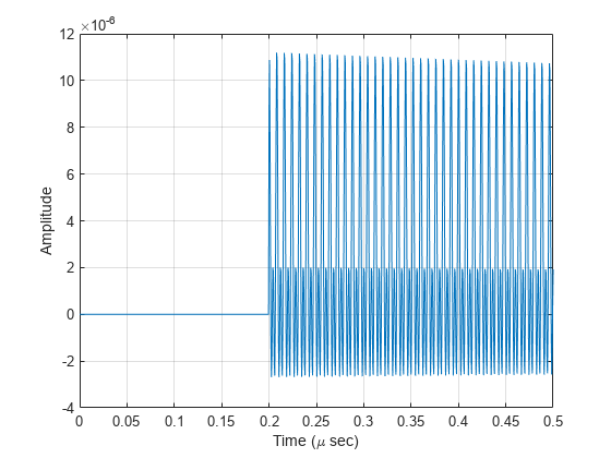
Propagate a wideband signal in a line-of-sight (LOS) channel from a radar at (0,0,0) meters to a target at (60,0,0) meters in medium fog. Set the fog liquid water density to 0.05 . Assume rain is falling at 5 mm/hr. The signal carrier frequency is 20 GHz. The signal is a sum of four cw tones at 19.75, 19.875, 20.125, and 20.25 GHz. Set the signal duration to 0.5 microsecond and the sample rate to 2.0 GHz. Assume the radar is stationary and the target approaches the radar at 40 m/s. The atmospheric temperature is 12°C and the dry air pressure is 101.300 kPa.
Set the signal parameters and create the transmitted signal.
c = physconst('LightSpeed');
fs = 2e9;
freq = [-0.25,-.125,0.0,0.125,0.25]*1e9;
fc = 20.0e9;
dt = 1/fs;
t = [0:dt:.5e-6];
sig = sum(exp(1i*2*pi*t.'*freq),2);
Specify the atmosphere parameters and create the phased.WidebandChannel System object™.
lwd = 0.05;
rainrate = 5.0;
dap = 101300.0;
temp = 12.0;
channel = phased.WidebandLOSChannel('SampleRate',fs,'PropagationSpeed',c,...
    'SpecifyAtmosphere',true,'OperatingFrequency',fc,'RainRate',rainrate,...
    'LiquidWaterDensity',lwd,'Temperature',temp,'DryAirPressure',dap);
Specify the radar and target positions and velocities.
xradar = [0,0,0].';
vradar = [0,0,0].';
xtgt = [60,0,0].';
vtgt = [-40,0,0].';
Propagate the signal.
prop_sig = channel(sig,xradar,xtgt,vradar,vtgt);
Plot the propagated signal. For a target range of 60 m, the propagation delay is 0.20 μs as shown in the plot.
plot(t*1e6,real(prop_sig))
grid
xlabel('Time (\mu sec)')
ylabel('Amplitude')
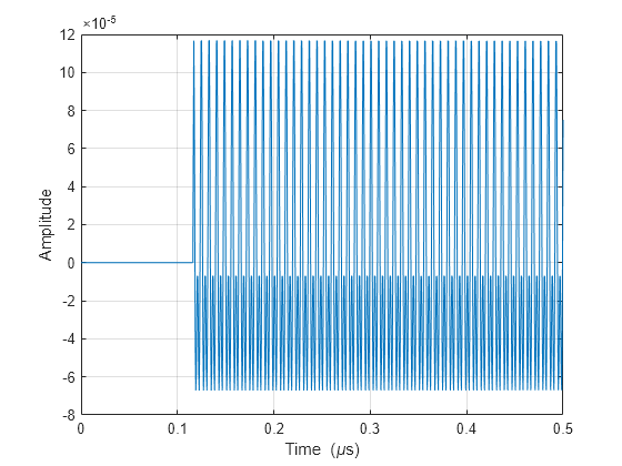
Propagate a wideband signal in a line-of-sight (LOS) channel from a radar at (0,0,0) meters to a target at (35,0,0) meters in medium fog. Set the fog liquid water density to 0.05 gm/m3. Assume rain is falling at 5 mm/hr. The signal carrier frequency is 20 GHz. The signal is a sum of four cw tones at 19.75, 19.875, 20.125, and 20.25 GHz. Set the signal duration to 0.5 μs and the sample rate to 2.0 GHz. Assume the radar is stationary and the target approaches the radar at 40 m/s. The atmospheric temperature is 12°C.
Set the signal parameters and create the transmitted signal.
c = physconst('LightSpeed');
fs = 2e9;
freq = [-0.25,-.125,0.125,0.25]*1e9;
fc = 20.0e9;
dt = 1/fs;
t = [0:dt:.5e-6];
sig = sum(exp(1i*2*pi*t.'*freq),2);
Specify the atmosphere parameters and create the phased.WidebandChannel System object™.
lwd = 0.05;
rainrate = 5.0;
temp = 12.0;
channel = phased.WidebandLOSChannel('SampleRate',fs,'PropagationSpeed',c,...
    'SpecifyAtmosphere',true,'OperatingFrequency',fc,'RainRate',rainrate,...
    'LiquidWaterDensity',lwd,'Temperature',temp);
Specify the radar and target positions and velocities.
xradar = [0,0,0].';
vradar = [0,0,0].';
xtgt = [35,0,0].';
vtgt = [-40,0,0].';
Propagate the signal.
prop_sig = channel(sig,xradar,xtgt,vradar,vtgt);
Plot the propagated signal. For a target range of 35 m, the propagation delay is 0.11 μs as seen in the plot.
plot(t*1e6,real(prop_sig))
grid
xlabel('Time ({\mu}s)')
ylabel('Amplitude')
Using the periodogram function with a Taylor window, plot the spectra of the original and propagated signals.
nfft = 1024;
nsamp = size(sig,1);
periodogram([sig prop_sig],taylorwin(nsamp),nfft,fs,'centered')
ylim([-200 0])
legend('transmitted','propagated')

More About
References
[1] Radiocommunication Sector of the International Telecommunication Union. Recommendation ITU-R P.676-10: Attenuation by atmospheric gases. 2013.
[2] Radiocommunication Sector of the International Telecommunication Union. Recommendation ITU-R P.840-6: Attenuation due to clouds and fog. 2013.
[3] Radiocommunication Sector of the International Telecommunication Union. Recommendation ITU-R P.838-3: Specific attenuation model for rain for use in prediction methods. 2005.
[4] Seybold, J. Introduction to RF Propagation. New York: Wiley & Sons, 2005.
[5] Skolnik, M. Introduction to Radar Systems, 3rd Ed. New York: McGraw-Hill, 2001.
Extended Capabilities
Version History
Introduced in R2016a
See Also
Functions
rangeangle|fogpl|gaspl|rainpl|fspl
Objects
phased.FreeSpace|phased.RadarTarget|phased.BackscatterRadarTarget|twoRayChannel(Radar Toolbox) |phased.WidebandFreeSpace|phased.LOSChannel