Analysis and Verification
Each element in the RF PCB Toolbox™ library has a set of analysis functions. Use these functions to analyze:
All the components in PCB Components Catalog.
Printed circuit board (PCB) components designed using
designfunction.Custom PCB components created using functions and objects in Custom Geometry and PCB Fabrication.
Use this category also to mesh the PCBs into discretized triangles and tetrahedrons for solving analysis equations. You can also compare RF PCB Toolbox simulations with fabricated PCBs, measured results, and technical articles.
Functions
Topics
Fundamental RF PCB Analysis
- Scattering Parameters or S-Parameters
Basics of S-parameters, how to analyze PCB components using S-parameters. - Behavioral Models
Accelerate circuit level analysis, behavioral s-parameter calculations, optimize layout and performance. - Characteristic Impedance of Transmission Lines
Characteristic impedance of transmission lines; even and odd mode impedances of coupled transmission lines.
Solvers
- Method of Moments Solver for Metal and Dielectric Structures
Method of Moments computation technique for metal and dielectrics in a PCB. - 2-D Field Solver
The 2-D field solver in RF PCB Toolbox™ allows you to model and analyze the cross-sections of multi-conductor transmission lines in a multi-layered dielectric above a ground plane like a microstrip line. - Eigenmode-Based Solver for PCB Vias
Wave generation and propagation in vias, circuit model, equations. - FEM-based Solver for RF Structures
This topic explains the use of a Finite-Element-Method-based solver to complex RF structures.
Featured Examples
Single Ended Via Analysis with Placement of Ground Return Vias for 40+ Gbps Signaling
Model the return path of single ended printed circuit board vias using the viaSingleEnded object.
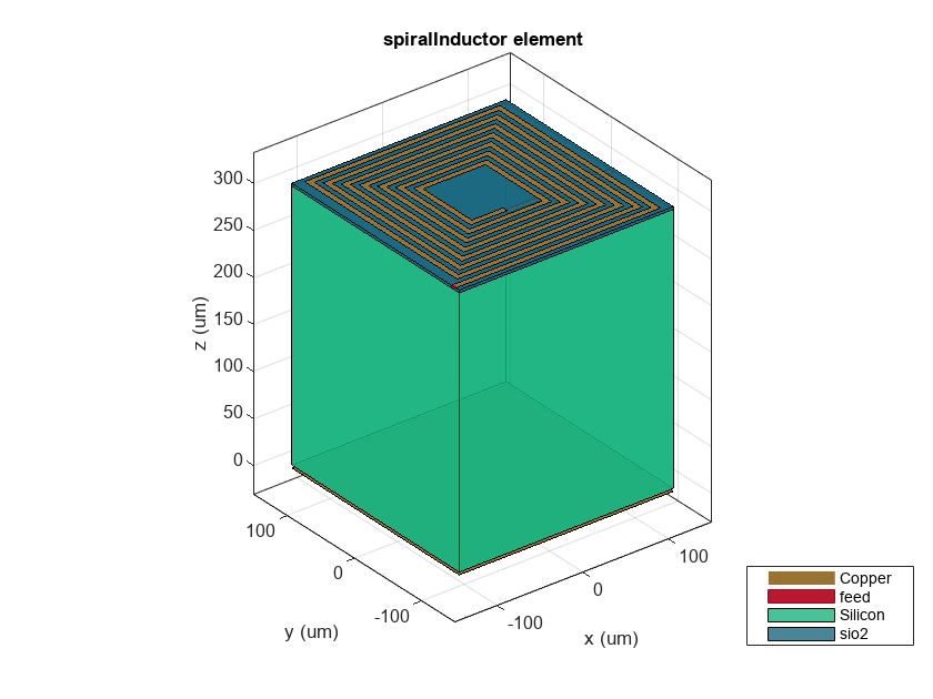
Surrogate Based Optimization of a Planar Spiral Inductor
Use an optimization based approach for designing a planar PCB spiral inductor. A surrogate optimization technique available in Global Optimization Toolbox™ is used as the optimizer. The spiral inductor material parameters and geometry gives rise to an effective inductance across the input and output ports. A rectangular spiral on a silicon substrate is chosen based on [1]. The target inductance to be achieved is 10 nH at a frequency of 3 GHz.
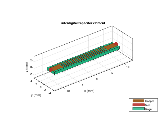
Model and Analyze Microstrip Interdigital Capacitor as Bandpass filter
Model and analyze a microstrip interdigital capacitor as a bandpass filter.
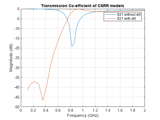
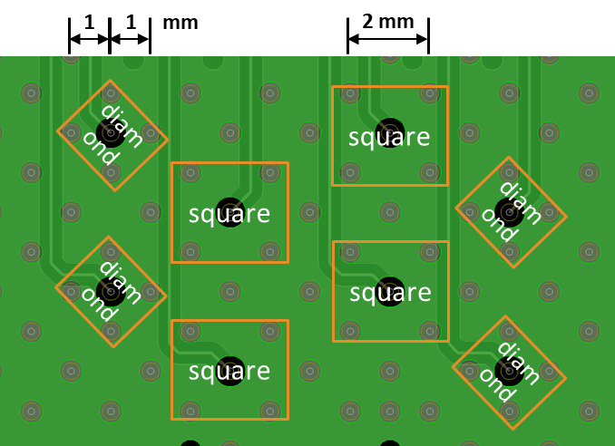
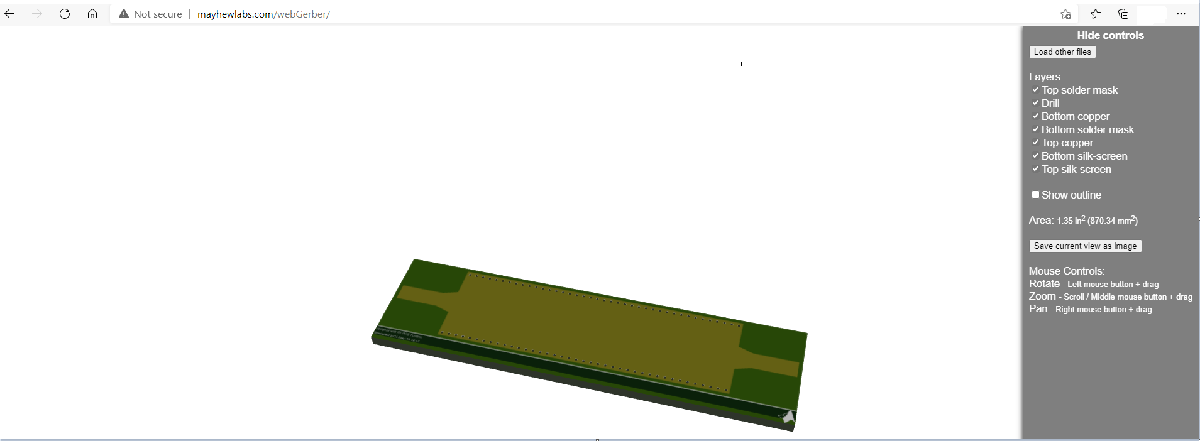
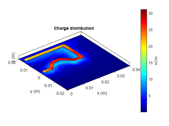
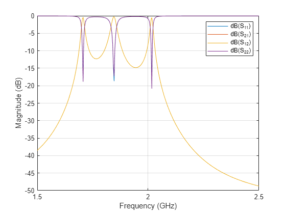
Create and Analyse Dual Characteristics of Complementary Split Ring Resonators from Gerber Files
Create and analyze of complementary split ring resonators from Gerber files.
Prototype, Design, and Analysis of SIW based Microstrip Tapered Transmission Line
Design and analyze SIW transmission line.
Create and Analyze PCB Interconnects using Custom Traces
Create and analyze PCB traces.
Design and Analysis of Hairpin Micro-Strip Line Bandpass Filter
Design and analyze a hairpin microstrip filter.