Main Content

Practical Introduction to Frequency-Domain Analysis

This example shows how to perform and interpret basic frequency-domain signal analysis. The example discusses the advantages of using frequency-domain versus time-domain representations of a signal and illustrates basic concepts using simulated and real data. The example answers basic questions such as: what is the meaning of the magnitude and phase of an FFT? Is my signal periodic? How do I measure power? Is there one, or more than one signal in this band?

Frequency-domain analysis is a tool of utmost importance in signal processing applications. Frequency-domain analysis is widely used in such areas as communications, geology, remote sensing, and image processing. While time-domain analysis shows how a signal changes over time, frequency-domain analysis shows how the signal's energy is distributed over a range of frequencies. A frequency-domain representation also includes information on the phase shift that must be applied to each frequency component in order to recover the original time signal with a combination of all the individual frequency components.

A signal can be converted between the time and frequency domains with a pair of mathematical operators called a transform. An example is the Fourier transform, which decomposes a function into the sum of a (potentially infinite) number of sine wave frequency components. The spectrum of frequency components is the frequency domain representation of the signal. The inverse Fourier transform converts the frequency domain function back to a time function. The fft and ifft functions in MATLAB® allow you to compute the Discrete Fourier transform (DFT) of a signal and the inverse of this transform respectively.

Magnitude and Phase Information of the FFT

The frequency-domain representation of a signal carries information about the signal's magnitude and phase at each frequency. This is why the output of the FFT computation is complex. A complex number, x, has a real part, xr, and an imaginary part, xi, such that x=xr+jxi. The magnitude of x is computed as (xr2+xi2), and the phase of x is computed as arctan(xi/xr). You can use MATLAB functions abs and angle to respectively get the magnitude and phase of any complex number.

Use an audio example to develop some insight on what information is carried by the magnitude and the phase of a signal. To do this, load an audio file containing 15 seconds of acoustic guitar music. The sample rate of the audio signal is 44.1 kHz.

Fs = 44100;
y = audioread("guitartune.wav");

Use fft to observe the frequency content of the signal.

NFFT = length(y);
Y = fft(y,NFFT);
F = ((0:1/NFFT:1-1/NFFT)*Fs).';

The output of the FFT is a complex vector containing information about the frequency content of the signal. The magnitude tells you the strength of the frequency components relative to other components. The phase tells you how all the frequency components align in time.

Plot the magnitude and the phase components of the frequency spectrum of the signal. The magnitude is conveniently plotted in a logarithmic scale (dB). The phase is unwrapped using the unwrap function so that we can see a continuous function of frequency.

magnitudeY = abs(Y);        % FFT magnitude
phaseY = unwrap(angle(Y));  % FFT phase

helperFrequencyAnalysisPlot1(F,magnitudeY,phaseY,NFFT)

Figure contains 2 axes objects. Axes object 1 with title Magnitude response of the audio signal, xlabel Frequency in kHz, ylabel dB contains an object of type line. Axes object 2 with title Phase response of the audio signal, xlabel Frequency in kHz, ylabel radians contains an object of type line.

You can apply an inverse Fourier transform to the frequency domain vector, Y, to recover the time signal. The "symmetric" flag tells ifft that you are dealing with a real-valued time signal so it will zero out the small imaginary components that appear on the inverse transform due to numerical inaccuracies in the computations. Notice that the original time signal, y, and the recovered signal, y1, are practically the same (the norm of their difference is on the order of 1e-14). The very small difference between the two is also due to the numerical inaccuracies mentioned above. Play and listen the inverse-Fourier-transformed signal y1.

y1 = ifft(Y,NFFT,"symmetric");
norm(y-y1)
ans = 
3.7851e-14
hplayer = audioplayer(y1,Fs);
play(hplayer);

To see the effects of changing the magnitude response of the signal, remove frequency components above 1 kHz directly from the FFT output (by making the magnitudes equal to zero) and listen to the effect this has on the sound of the audio file. Removing high frequency components of a signal is referred to as lowpass filtering.

Ylp = Y;
Ylp(F>=1000 & F<=Fs-1000) = 0;

helperFrequencyAnalysisPlot1(F,abs(Ylp),unwrap(angle(Ylp)), ...
    NFFT,"Frequency components above 1 kHz have been zeroed")
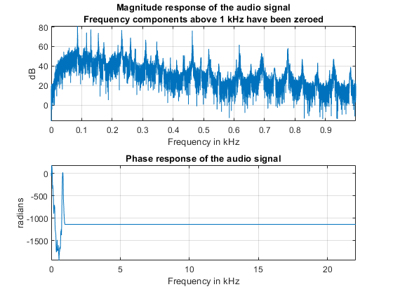
Figure contains 2 axes objects. Axes object 1 with title Magnitude response of the audio signal Frequency components above 1 kHz have been zeroed, xlabel Frequency in kHz, ylabel dB contains an object of type line. Axes object 2 with title Phase response of the audio signal, xlabel Frequency in kHz, ylabel radians contains an object of type line.

Get the filtered signal back into time domain using ifft.

ylp = ifft(Ylp,"symmetric");

Play the signal. You can still hear the melody but it sounds like if you had covered your ears (you filter high frequency sounds when you do this). Even though guitars produce notes that are between 400 and 1 kHz, as you play a note on a string, the string also vibrates at multiples of the base frequency. These higher frequency components, referred to as harmonics, are what give the guitar its particular tone. When you remove them, you make the sound seem "opaque".

hplayer = audioplayer(ylp, Fs);
play(hplayer);

The phase of a signal has important information about when in time the notes of the song appear. To illustrate the importance of phase on the audio signal, remove the phase information completely by taking the magnitude of each frequency component. Note that by doing this you keep the magnitude response unchanged.

% Take the magnitude of each FFT component of the signal
Yzp = abs(Y);
helperFrequencyAnalysisPlot1(F,abs(Yzp), ...
    unwrap(angle(Yzp)),NFFT,[],"Phase has been set to zero")

Figure contains 2 axes objects. Axes object 1 with title Magnitude response of the audio signal, xlabel Frequency in kHz, ylabel dB contains an object of type line. Axes object 2 with title Phase response of the audio signal Phase has been set to zero, xlabel Frequency in kHz, ylabel radians contains an object of type line.

Get the signal back in the time domain and play the audio. You cannot recognize the original sound at all. The magnitude response is the same, no frequency components have been removed this time, but the order of the notes has disappeared completely. The signal now consists of a group of sinusoids all aligned at time equal to zero. In general, phase distortions caused by filtering can damage a signal to the point of rendering it unrecognizable.

yzp = ifft(Yzp,"symmetric");
hplayer = audioplayer(yzp, Fs);
play(hplayer);

Finding Signal Periodicities

The frequency domain representation of a signal allows you to observe several characteristics of the signal that are either not easy to see, or not visible at all when you look at the signal in the time domain. For instance, frequency-domain analysis becomes useful when you are looking for cyclic behavior of a signal.

Analyzing Cyclic Behavior of the Temperature in an Office Building

Consider a set of temperature measurements in an office building during the winter season. Measurements were taken every 30 minutes for about 16.5 weeks. Look at the time domain data with the time axis scaled to weeks. Could there be any periodic behavior on this data?

load officetemp.mat
Fs = 1/(60*30);   % Sample rate is 1 sample every 30 minutes
t = (0:length(temp)-1)/Fs;

helperFrequencyAnalysisPlot2(t/(60*60*24*7),temp, ...
  "Time (weeks)","Temperature (\circF)")
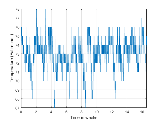
Figure contains an axes object. The axes object with xlabel Time (weeks), ylabel Temperature ( degree F) contains an object of type line.

It is almost impossible to know if there is any cyclic behavior on the office temperatures by looking at the time-domain signal. However, the cyclic behavior of the temperature becomes evident if we look at its frequency-domain representation.

Obtain the frequency-domain representation of the signal. If you plot the magnitude of the FFT output with a frequency axis scaled to cycles/week, you can see that there are two spectral lines that are clearly larger than any other frequency component. One spectral line lies at 1 cycle/week, the other one lies at 7 cycles/week. This makes sense given that the data comes from a temperature-controlled building on a 7 day calendar. The first spectral line indicates that building temperatures follow a weekly cycle with lower temperatures on the weekends and higher temperatures during the week. The second line indicates that there is also a daily cycle with lower temperatures during the night and higher temperatures during the day.

NFFT = length(temp);              % Number of FFT points
F = (0 : 1/NFFT : 1/2-1/NFFT)*Fs; % Frequency vector

TEMP = fft(temp,NFFT);            
TEMP(1) = 0; % remove the DC component for better visualization

helperFrequencyAnalysisPlot2(F*60*60*24*7,abs(TEMP(1:NFFT/2)), ...
  "Frequency (cycles/week)","Magnitude",[],[],[0 10])
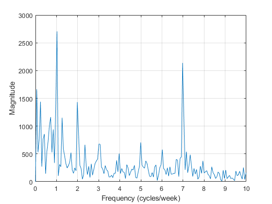
Figure contains an axes object. The axes object with xlabel Frequency (cycles/week), ylabel Magnitude contains an object of type line.

Measuring Power

The periodogram function computes the signal's FFT and normalizes the output to obtain a power spectral density, PSD, or a power spectrum from which you can measure power. The PSD describes how the power of a time signal is distributed with frequency, it has units of watts/Hz. You compute the power spectrum by integrating each point of the PSD over the frequency interval at which that point is defined (i.e. over the resolution bandwidth of the PSD). The units of the power spectrum are watts. You can read power values directly from the power spectrum without having to integrate over an interval. Note that the PSD and power spectrum are real, so they do not contain any phase information.

Measuring Harmonics at the Output of a Non-Linear Power Amplifier

Load the data measured at the output of a power amplifier that has third order distortion of the form vo=vi+0.75vi2+0.5vi3, where vo is the output voltage and vi is the input voltage. The data was captured with a sample rate of 3.6 kHz. The input vi consists of a 60 Hz sinusoid with unity amplitude. Due to the nature of the non-linear distortion, you should expect the amplifier output signal to contain a DC component, a 60 Hz component, and second and third harmonics at 120 and 180 Hz.

Load 3600 samples of the amplifier output, compute the power spectrum, and plot the result in a logarithmic scale (decibels-watts or dBW).

load ampoutput1.mat
Fs = 3600;
NFFT = length(y);

% Power spectrum is computed when you pass a "power" flag input
[P,F] = periodogram(y,[],NFFT,Fs,"power");   

helperFrequencyAnalysisPlot2(F,10*log10(P),"Frequency (Hz)", ...
  "Power spectrum (dBW)",[],[],[-0.5 200])
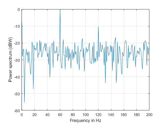
Figure contains an axes object. The axes object with xlabel Frequency (Hz), ylabel Power spectrum (dBW) contains an object of type line.

The plot of the power spectrum shows three of the four expected peaks at DC, 60, and 120 Hz. It also shows several more spurious peaks that must be caused by noise in the signal. Note that the 180 Hz harmonic is completely buried in the noise.

Measure the power of the visible expected peaks:

PdBW = 10*log10(P);
power_at_DC_dBW = PdBW(F==0)
power_at_DC_dBW = 
-7.8873
[peakPowers_dBW, peakFreqIdx] = findpeaks(PdBW,MinPeakHeight=-11);
peakFreqs_Hz = F(peakFreqIdx)
peakFreqs_Hz = 2×1

    60
   120

peakPowers_dBW
peakPowers_dBW = 2×1

   -0.3175
  -10.2547

Improving Power Measurements for Noisy Signals

As seen on the plot above, the periodogram shows several frequency peaks that are not related to the signal of interest. The spectrum looks very noisy. The reason for this is that you only analyzed one short realization of the noisy signal. Repeating the experiment several times and averaging would remove the spurious spectral peaks and yield more accurate power measurements. You can achieve this averaging using the pwelch function. This function will take a large data vector, break it into smaller segments of a specified length, compute as many periodograms as there are segments, and average them. As the number of available segments increases, the pwelch function will yield a smoother power spectrum (less variance) with power values closer to the expected values.

Load a larger observation consisting of 500e3 points of the amplifier output. Keep the number of points used to perform the FFTs as 3600 so that floor(500e3/3600) = 138 FFTs are averaged to obtain the power spectrum.

load ampoutput2.mat
SegmentLength = NFFT; 

% Power spectrum is computed when you pass a "power" flag input
[P,F] = pwelch(y,ones(SegmentLength,1),0,NFFT,Fs,"power");

helperFrequencyAnalysisPlot2(F,10*log10(P),"Frequency (Hz)", ...
  "Power spectrum (dBW)",[],[],[-0.5 200])
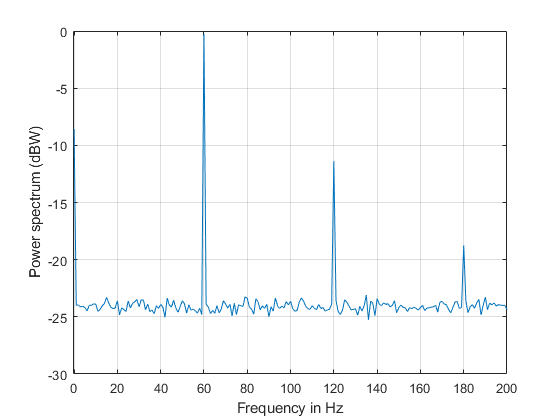
Figure contains an axes object. The axes object with xlabel Frequency (Hz), ylabel Power spectrum (dBW) contains an object of type line.

As seen on the plot, pwelch effectively removes all the spurious frequency peaks caused by noise. The spectral component at 180 Hz that was buried in noise is now visible. Averaging removes variance from the spectrum and this effectively yields more accurate power measurements.

Measuring Total Average Power and Power Over a Frequency Band

Measuring the total average power of a time-domain signal is an easy and common task. For the amplifier output signal, y, the total average power is computed in the time domain as:

pwr = sum(y.^2)/length(y) % in watts
pwr = 
8.1697

In the frequency-domain, the total average power is computed as the sum of the power of all the frequency components of the signal. The value of pwr1 consists of the sum of all the frequency components available in the power spectrum of the signal. The value agrees with the value of pwr computed above using the time domain signal:

pwr1 = sum(P) % in watts
pwr1 = 
8.1698

But what if you wanted to measure the total power available over a band of frequencies? You can use the bandpower function to compute the power over any desired frequency band. You can pass the time-domain signal directly as an input to this function to obtain the power over a specified band. In this case, the function will estimate the power spectrum with the periodogram method.

Compute the power over the 50 Hz to 70 Hz band. The result will include the 60 Hz power plus the noise power over the band of interest:

pwr_band = bandpower(y,Fs,[50 70]);
pwr_band_dBW = 10*log10(pwr_band) % dBW
pwr_band_dBW = 
0.0341

If you want to control the computation of the power spectrum used to measure the power in a band, you can pass a PSD vector to the bandpower function. For instance, you can use the pwelch function as you did before to compute the PSD and ensure averaging of the noise effects:

% Power spectral density is computed when you specify the "psd" option
[PSD,F]  = pwelch(y,ones(SegmentLength,1),0,NFFT,Fs,"psd");
pwr_band1 = bandpower(PSD,F,[50 70],"psd");
pwr_band_dBW1 = 10*log10(pwr_band1) % dBW
pwr_band_dBW1 = 
0.0798

Finding Spectral Components

A signal might be composed of one or more frequency components. The ability to observe all the spectral components depends on the frequency resolution of your analysis. The frequency resolution or resolution bandwidth of the power spectrum is defined as R = Fs/N, where N is the length of the signal observation. Only spectral components separated by a frequency larger than the frequency resolution will be resolved.

Analyzing a Building's Earthquake Vibration Control System

Active Mass Driver (AMD) control systems are used to reduce vibration in a building under an earthquake. An active mass driver is placed on the top floor of the building and, based on displacement and acceleration measurements of the building floors, a control system sends signals to the driver so that the mass moves to attenuate ground disturbances. Acceleration measurements were recorded on the first floor of a three story test structure under earthquake conditions. Measurements were taken without the active mass driver control system (open loop condition), and with the active control system (closed loop condition).

Load the acceleration data and compute the power spectrum for the acceleration of the first floor. The length of the data vectors is 10e3 and the sample rate is 1 kHz. Use pwelch with segments of length 64 data points to obtain floor(10e3/64) = 156 FFT averages and a resolution bandwidth of Fs/64 = 15.625 Hz. As was shown before, averaging reduces noise effects and yields more accurate power measurements. Use 512 FFT points. Using NFFT > N effectively interpolates frequency points rendering a more detailed spectrum plot (this is achieved by appending NFFT-N zeros at the end of the time signal and taking the NFFT-point FFT of the zero padded vector).

The open loop and close loop acceleration power spectra show that when the control system is active, the acceleration power spectrum decreases between 4 and 11 dB. The maximum attenuation occurs at about 23.44 kHz. An 11 dB reduction means that the vibration power is reduced by a factor of 12.6. The total power is reduced from 0.1670 to 0.059 watts, a factor of 2.83.

load quakevibration.mat

Fs = 1e3;                 % sample rate
NFFT = 512;               % number of FFT points
segmentLength = 64;       % segment length

% open loop acceleration power spectrum
[P1_OL,F] = pwelch(gfloor1OL,ones(segmentLength,1),0,NFFT,Fs,"power"); 

% closed loop acceleration power spectrum
P1_CL     = pwelch(gfloor1CL,ones(segmentLength,1),0,NFFT,Fs,"power"); 

helperFrequencyAnalysisPlot2(F,10*log10([(P1_OL) (P1_CL)]),...
  "Frequency (Hz)","Acceleration Power Spectrum (dB)",...
  "Resolution bandwidth = 15.625 Hz",["Open" "Closed"]+" loop",[0 100])

Figure contains an axes object. The axes object with title Resolution bandwidth = 15.625 Hz, xlabel Frequency (Hz), ylabel Acceleration Power Spectrum (dB) contains 2 objects of type line. These objects represent Open loop, Closed loop.

You are analyzing vibration data and you know that vibrations have a cyclic behavior. Then how is it that the spectrum plots shown above do not contain any sharp spectral lines typical of cyclic behavior? Maybe you are missing those lines because they are not resolvable with the resolution obtained with 64 point segment lengths? Increase the frequency resolution to see if there are spectral lines that were not resolvable before. Do this by increasing the data segment length used in the pwelch function to 512 points. This yields a new resolution of Fs/512 = 1.9531 Hz. In this case, the number of FFT averages is reduced to floor(10e3/512) = 19. Clearly, there is a trade-off between number of averages and frequency resolution when using pwelch. Keep the number of FFT points equal to 512.

NFFT = 512;            % number of FFT points
segmentLength = 512;   % segment length

[P1_OL,F] = pwelch(gfloor1OL,ones(segmentLength,1),0,NFFT,Fs,"power"); 
P1_CL     = pwelch(gfloor1CL,ones(segmentLength,1),0,NFFT,Fs,"power"); 

helperFrequencyAnalysisPlot2(F,10*log10([(P1_OL) (P1_CL)]),  ...
  "Frequency in Hz","Acceleration Power Spectrum in dB", ...
  "Resolution bandwidth = 1.95 Hz",{"Open loop", "Closed loop"},[0 100])
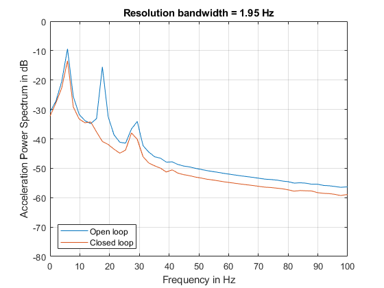
Figure contains an axes object. The axes object with title Resolution bandwidth = 1.95 Hz, xlabel Frequency in Hz, ylabel Acceleration Power Spectrum in dB contains 2 objects of type line. These objects represent Open loop, Closed loop.

Notice how the increase in frequency resolution allows you to observe three peaks on the open loop spectrum and two on the close loop spectrum. These peaks were not resolvable before. The separation between the peaks on the open loop spectrum is about 11 Hz which is smaller than the frequency resolution obtained with segments of length 64 but larger than the resolution obtained with segments of length 512. The cyclic behavior of the vibrations is now visible. The main vibration frequency is at 5.86 Hz, and the evenly spaced frequency peaks suggest that they are harmonically related. While it has already been observed that the control system reduces the overall power of the vibrations, the higher resolution spectra shows that another effect of the control system is to notch the harmonic component at 17.58 Hz. So the control system not only reduces the vibration but also brings it closer to a sinusoid.

It is important to note that frequency resolution is determined by the number of signal points, not by the number of FFT points. Increasing the number of FFT points interpolates the frequency data to give you more details on the spectrum but it does not improve resolution.

Conclusions

In this example you learned how to perform frequency-domain analysis of a signal using the fft, ifft, periodogram, pwelch, and bandpower functions. You understood the complex nature of the FFT and what is the information contained in the magnitude and the phase of the frequency spectrum. You saw the advantages of using frequency domain data when analyzing the periodicity of a signal. You learned how compute the total power or power over a particular band of frequencies of a noisy signal. You understood how increasing the frequency resolution of the spectrum allows you to observe closely spaced frequency components and you learned about the tradeoff between frequency resolution and spectral averaging.

Further Reading

For more information on frequency-domain analysis, see Spectral Analysis.

Reference: J.G. Proakis and D. G. Manolakis, "Digital Signal Processing. Principles, Algorithms, and Applications", Prentice Hall, 1996.

Appendix

This example uses the following helper functions:

See Also

| | |