Transmit Signal Data Between Components Linked to Behavior Models
A System Composer™ architecture model represents a system that you can simulate by adding Simulink® behaviors to components. First, you assign interfaces to ports on the components. Then, you can design these interfaces so that when they propagate to the linked Simulink behavior model, information is exchanged between components as you expect.
You can use System Composer interfaces with Simulink buses, and use System Composer data interfaces and data elements with Simulink component behaviors.
You can also link Simulink behaviors to System Composer components using port elements and value types.
Using System Composer Interfaces with Simulink Buses
System Composer interfaces relate to Simulink dictionary data types. The table provides information about each artifact and how to work with them in Simulink.
Compare System Composer and Simulink Interfaces
| System Composer | Simulink | More Information |
|---|---|---|
| Data interface | Virtual or nonvirtual bus | Group Signals or Messages into Virtual Buses |
| Data element | Bus element | Simplify Subsystem and Model Interfaces with Bus Element Ports |
| Port element | Bus element | Simplify Subsystem and Model Interfaces with Bus Element Ports |
| Value type | Value type | Specify Common Set of Signal Properties as Value Type |
For information about how to use physical interfaces, see Implement Component Behavior Using Simscape.
For information about how to use service interfaces, see Service Interfaces Overview.
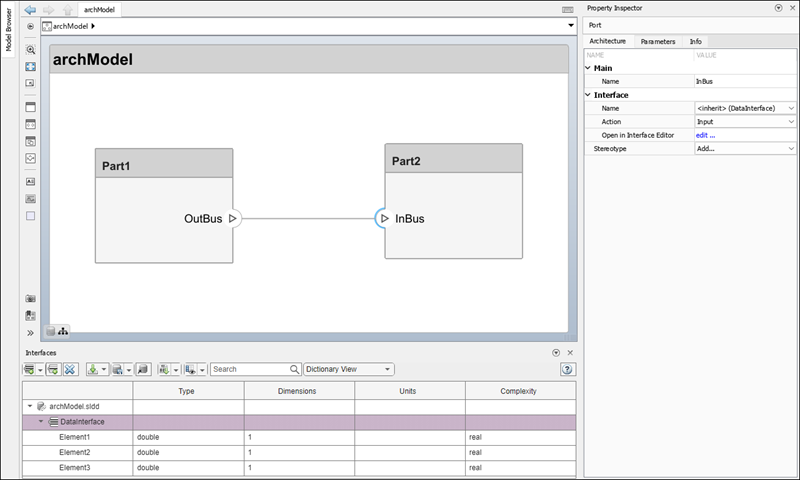
Create Interfaces in Architecture Models
To prepare your system for Simulink component behaviors, create data interfaces in an architecture model and assign the data interfaces to ports. A data interface defines the kind of information that flows through a port. You can assign the same interface to multiple ports. A data interface can be composite, meaning that it can include data elements that describe the properties of an interface signal. For more information about data interfaces, see Define Port Interfaces Between Components.
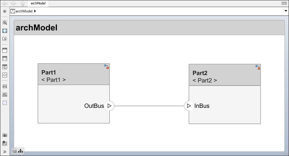
Link Simulink Component Behaviors and Design Buses
To link Simulink behaviors to components Part1 and
Part2, right-click each component and select Create
behavior and then Simulink Behavior. For
more information about Simulink behaviors, see Implement Component Behavior Using Simulink.
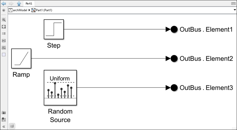
After linking empty Simulink models, you can populate the models.
For the Simulink model Part1, create three source blocks. Then, use
Out Bus Element blocks to pass the
values onto the OutBus port. For more information on using Out Bus
Element blocks, see Connect Multiple Output Signals to One Port.
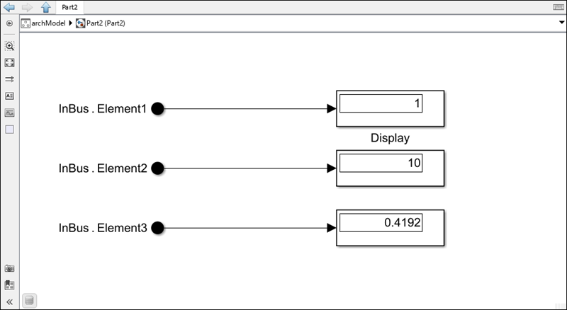
You can use System Composer architectures to connect two components and use interfaces on ports to
transfer the values to the Part2 component. The
Part2
Simulink behavior model contains In Bus Element blocks. After simulating the model, the values propagate the
Display blocks.
Link Simulink Behavior to Port Elements and Value Types
When ports are typed by port elements or value types, you can also use Inport and Outport blocks in Simulink to propagate the values.
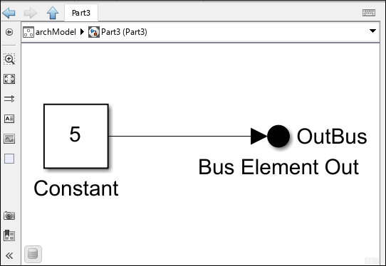
In this example, the OutBus port on the Part3
component and the InBus port on the Part4 component are
typed by a value type. The Out1 port on the Part4
component is typed by a data interface, with the architecture port chevron showing
OutBus.Element1.x, which is one of many nested data
elements.
The Part3 component links to a Simulink behavior that defines a Constant block to propagate the value 5 to the value
type assigned to the port.
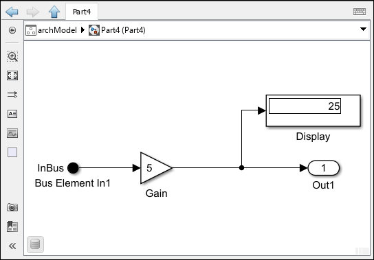
When Part3 connected to Part4 executes, the
Gain block with a value of
5 outputs the final value of 25 assigned to
the port element on Out1.
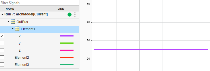
From the Simulation tab, access the Simulation Data
Inspector. Visualize the signal for the x coordinate to
see a value of 25 from the simulation for the
OutBus.Element1.x port element.
See Also
Functions
addInterface|removeInterface|addElement|getSubElement|getPortElement|removeElement|connect|setInterface|addValueType