estimateCameraRobotTransform
Estimate pose of camera relative to robot using hand-eye calibration
Since R2025a
Description
relativePose = estimateCameraRobotTransform(cameraExtrinsics,gripperPose,configuration)relativePose of a camera relative to a robot frame
using hand-eye calibration for a moving or stationary configuration.
The value of cameraExtrinsics is the pose of the calibration object
relative to the camera. gripperPose is the pose of the robot gripper
relative to the robot base.
Examples
Load a MAT file that contains this robot hand-eye calibration data.
intrinsics— Intrinsic parameters of the camera, stored as acameraIntrinsicsobject. These parameters have been estimated using the process from the Using the Single Camera Calibrator App topic.camExtrinsics: Positions and orientations of the calibration pattern relative to the camera in 15 calibration images, stored as a 15-by-1 vector ofrigidtform3dobjects. These extrinsic parameters have been computed from the images containing the calibration pattern by using theestimateExtrinsicsfunction with the estimatedintrinsics.gripperPoses: Positions and orientations of the robot gripper, relative to the robot base, while capturing the 15 calibration images, stored as a 15-by-1 vector ofrigidtform3dobjects.
ld = load("stationaryCameraCalibrationData.mat");Perform robot hand-eye calibration for the stationary-camera configuration to estimate the camera pose relative to robot base.
camPose = estimateCameraRobotTransform(ld.camExtrinsics,ld.gripperPoses,"stationary-camera");To verify the calibration results, follow these steps:
Place a detectable object, such a checkerboard calibration pattern, near the robot and record the distance from the object to the robot base.
Capture an image of the object from the camera.
Estimate the camera extrinsic parameters for the captured image.
Transform object keypoints detected in image coordinates to world coordinates.
Verify that the transformed world coordinates match the distance recorded in the first step.
This stationary camera configuration has already been used to capture an image of a calibration checkerboard. Load the captured checkerboard image. Load the captured checkerboard image.
I = imread("stationaryCameraSampleImage.jpg");Detect checkerboard keypoints, generate corresponding world points in the checkerboard coordinate system, and estimate the camera extrinsic parameters for the captured image.
[imagePts,patternDims] = detectCheckerboardPoints(I);
squareSize = 0.029; % in meters
patternWorldPts2D = patternWorldPoints("checkerboard",patternDims,squareSize);
cameraExtrinsics = estimateExtrinsics(imagePts,patternWorldPts2D,ld.intrinsics);
Using the cameraExtrinsics and camPose objects, transform any image coordinates on the same plane as the calibration pattern to world coordinates in the robot coordinate system. Use the checkerboard keypoints is used as the object of interest.
Transform object points from the image coordinate system to the camera coordinate system.
objectWorldPts2D = img2world2d(imagePts,cameraExtrinsics,ld.intrinsics);
objectWorldPts3D = padarray(objectWorldPts2D,[0 1],"post");
Use camPose to find the transformation of the camera relative to the robot base frame, and transform the object points to the robot base frame.
pointsToBasePose = rigidtform3d(camPose.A * cameraExtrinsics.A);
objectPts = transformPointsForward(pointsToBasePose,objectWorldPts3D);
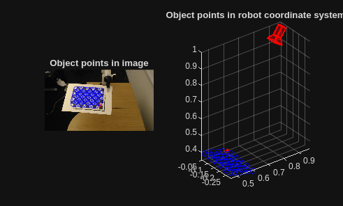
Visualize the object keypoints detected in the image and transformed to the robot coordinate system. Display the first checkerboard keypoint with a different marker and color.
tiledlayout(1,2)

nexttile
imshow(I)
hold on
plot(imagePts(1,1),imagePts(1,2),"r*");
plot(imagePts(2:end,1),imagePts(2:end,2),"bo");
title("Object points in image")

nexttile
plotCamera(AbsolutePose=camPose,Size=.03)
hold on
plot3(objectPts(1,1),objectPts(1,2),objectPts(1,3),"r*")
plot3(objectPts(2:end,1),objectPts(2:end,2),objectPts(2:end,3),"bo")
axis equal
grid on
title("Object points in robot coordinate system")
Load a MAT file that contains this robot hand-eye calibration data.
intrinsics— Intrinsic parameters of the camera, stored as acameraIntrinsicsobject. These parameters have been estimated using the process from the Using the Single Camera Calibrator App topic.camExtrinsics: Positions and orientations of the calibration pattern relative to the camera in 15 calibration images, stored as a 15-by-1 vector ofrigidtform3dobjects. These extrinsic parameters have been computed from the images containing the calibration pattern by using theestimateExtrinsicsfunction with the estimatedintrinsics.gripperPoses: Positions and orientations of the robot gripper, relative to the robot base, while capturing the 15 calibration images, stored as a 15-by-1 vector ofrigidtform3dobjects.
ld1 = load("movingCameraCalibrationData.mat");Perform robot hand-eye calibration for the moving-camera configuration to estimate the camera pose relative to the robot gripper.
camPose = estimateCameraRobotTransform(ld1.camExtrinsics,ld1.gripperPoses,"moving-camera");To verify the calibration results, follow these steps:
Place a detectable object, such a checkerboard calibration pattern, near the robot and record the distance from the object to the robot base.
Capture an image of the object from the camera.
Record the robot gripper pose relative to the robot base while capturing that image.
Estimate the camera extrinsic parameters for the captured image.
Transform object keypoints detected in image coordinates to world coordinates.
Verify that the transformed world coordinates match the distance recorded in the first step.
This moving camera configuration has already been used to capture an image of a calibration checkerboard and record the pose of the robot gripper relative to the robot base. Load the captured checkerboard image and the corresponding robot gripper pose.
I = imread("movingCameraSampleImage.jpg");
ld2 = load("movingCameraSamplePose.mat");
Detect checkerboard keypoints, generate corresponding world points in the checkerboard coordinate system, and estimate the camera extrinsic parameters for the captured image.
[imagePts,patternDims] = detectCheckerboardPoints(I);
squareSize = 0.029; % in meters
patternWorldPts2D = patternWorldPoints("checkerboard",patternDims,squareSize);
cameraExtrinsics = estimateExtrinsics(imagePts,patternWorldPts2D,ld1.intrinsics);
Using the cameraExtrinsics and camPose objects, transform any image coordinates on the same plane as the calibration pattern to world coordinates in the robot coordinate system. Use the checkerboard keypoints is used as the object of interest.
Transform object points from the image coordinate system to the camera coordinate system.
objectWorldPts2D = img2world2d(imagePts,cameraExtrinsics,ld1.intrinsics);
objectWorldPts3D = padarray(objectWorldPts2D,[0 1],"post");
Use camPose to find the transformation of the camera relative to the robot base frame, and transform the object points to the robot base frame.
camToBasePose = rigidtform3d(ld2.gripperPose * camPose.A);
pointsToBasePose = rigidtform3d(camToBasePose.A * cameraExtrinsics.A);
objectPts = transformPointsForward(pointsToBasePose, objectWorldPts3D);
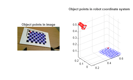
Visualize the object keypoints detected in the image and transformed to the robot coordinate system. Display the first checkerboard keypoint with a different marker and color.
tiledlayout(1,2)

nexttile
imshow(I)
hold on
plot(imagePts(1,1),imagePts(1,2),"r*");
plot(imagePts(2:end,1),imagePts(2:end,2),"bo");
title("Object points in image")

nexttile
plotCamera(AbsolutePose=camToBasePose,Size=.03)
hold on
plot3(objectPts(1,1),objectPts(1,2),objectPts(1,3),"r*")
plot3(objectPts(2:end,1),objectPts(2:end,2),objectPts(2:end,3),"bo")
axis equal
grid on
title("Object points in robot coordinate system")
Input Arguments
Output Arguments
Algorithms
The hand-eye calibration method originated from a seminal paper by Tsai and Lenz [1]. Their approach is based on solving the equation AX = XB, where:
A is the transformation of the robot gripper from one position to the next.
B is the transformation of the camera or the calibration target (whichever is moving with the robot gripper) from one position to the next.
X is the unknown transformation.
The approach uses the least squares method to solve the equation AX = XB. To obtain the intermediate transformations A and B, you must have information about the robot gripper pose and the camera pose at two different locations. In general, you can calibrate any sensors that can establish the relationship AX = XB using the hand-eye calibration method.
References
[1] Tsai, R.Y., and R.K. Lenz. "A New Technique for Fully Autonomous and Efficient 3D Robotics Hand/Eye Calibration." IEEE Transactions on Robotics and Automation 5, no. 3 (1989): 345-58.
Version History
Introduced in R2025a
See Also
Apps
Functions
getTransform(Robotics System Toolbox) |estimateExtrinsics|extr2pose|estrelpose