Spacecraft Pose Estimation Using HRNet Keypoint Detector and PnP Solver
This example shows how to detect keypoints on a spacecraft using a pretrained HRNet deep learning network and then use the detected keypoints to estimate the pose of the spacecraft. This example uses images from the SPEED-UE-Cube spacecraft image dataset to demonstrate spacecraft detection and pose estimation. In this example, you will:
Use a pre-trained YOLOv4 object detector to detect spacecraft in an image.
Perform transfer learning to adapt a pretrained HRNet keypoint detector for detecting keypoints on a spacecraft image.
Use the
estworldposefunction to solve the Perspective-n-Point (PnP) problem and estimate the spacecraft’s pose from the detected keypoints.
This example also requires the Aerospace Toolbox™.
Download Pretrained Detectors and Spacecraft Image Dataset
Download the pretrained detectors for keypoint detection and object detection, along with the SPEED-UE-Cube spacecraft image dataset, by using the helperDownloadDatasetAndDetectors helper function.
downloadFolder = pwd;
[pretrainedKeypointDetector,pretrainedObjectDetector,dataset] = helperDownloadDatasetAndDetectors(downloadFolder);
Load Spacecraft Reference Keypoints
This example uses a 3U CubeSat model as the reference model. The CubeSat is represented by 11 keypoints: 4 for the panels, 4 for the main body, and 3 for the antennas. These keypoints are nonsymmetrical in nature and hence, they can be easily identified and tracked. It also helps to accurately estimate the pose of the spacecraft. The connections between the keypoints form a wireframe or skeleton of the spacecraft. You can derive these keypoints and establish the keypoint connections from a CAD model of the spacecraft.
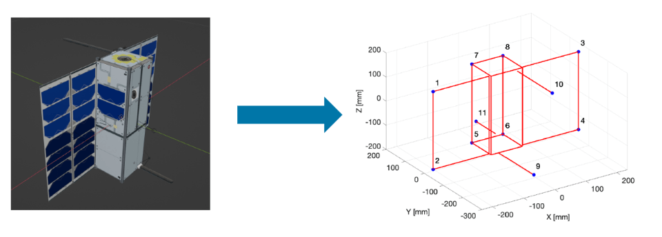
Load the reference keypoints into the MATLAB® workspace.
load("cubesatPoints.mat","sat3dPoints");
pointsSpeedCubeBodyRef = sat3dPoints';
Load Camera Parameters
The image dataset used in this example consists of synthetically generated images of the CubeSat. These images are captured from the perspective of a camera on the ego spacecraft. The PnP solver uses camera parameters, such as focal length and principal point, to estimate the pose of the spacecraft.
Load the camera parameters associated with the dataset into the MATLAB workspace. The camera parameters loaded in the workspace are defined in OpenCV format. Use the helperCameraParametersCubesat helper function to convert the camera intrinsics parameters from OpenCV to MATLAB cameraIntrinsics object.
camera = jsondecode(fileread("camera.json"));
[cameraParamMatlab,intrinsicsOpenCV] = helperCameraParametersCubesat(camera);
Inspect the properties of camera intrinsics object.
cameraParamMatlab
cameraParamMatlab =
  cameraIntrinsics with properties:

             FocalLength: [2.9886e+03 2.9883e+03]
          PrincipalPoint: [961 601]
               ImageSize: [1920 1200]
        RadialDistortion: [3×1 double]
    TangentialDistortion: [2×1 double]
                    Skew: 0
                       K: [3×3 double]
Load Spacecraft Dataset
Loads the .mat file containing the dataset into the MATLAB workspace.
data = load(dataset);
Extract the ground truth table from the loaded data and inspect first few rows of the table.
spaceCraftPoseDataset = data.SpacecraftGroundTruth;
spaceCraftPoseDataset(1:4,:)
ans=4×5 table
    "img000021.jpg"    [518,166,631,929]    11×2 double    [0.1424,-0.0374,0.9774,-0.1519]      [0.0032,0.0351,1.7361]
    "img000029.jpg"     [604,78,747,653]    11×2 double     [0.4668,-0.4167,0.7163,0.3089]     [0.0132,-0.1354,2.2325]
    "img000048.jpg"    [491,202,764,553]    11×2 double    [0.2655,-0.5355,0.7791,-0.1893]    [-0.0485,-0.0434,2.1329]
    "img000109.jpg"    [802,497,215,247]    11×2 double     [0.1299,0.2414,0.7818,-0.5600]     [-0.0617,0.0198,5.1687]
The dataset is structured as a table with three columns:
The first column contains the filenames of the images.
The second column contains bounding boxes for the spacecraft in the images.
The third column contains keypoint locations, represented as N-by-2 matrices where N is the number of keypoints for the spacecraft.
Each image is assumed to contain only one spacecraft, meaning each row corresponds to one object. If a custom dataset includes images with multiple spacecraft, you must create a separate row for each object in the image to maintain consistency.
Update the imageFilename column to include the full path to each image file.
spaceCraftPoseDataset.imageFilename = fullfile(downloadFolder,"SpacecraftDataset/",spaceCraftPoseDataset.imageFilename);Load Pretrained Object Detector
Load a pretrained YOLO v4 object detector to detect spacecraft in an image. The YOLO v4 object detector is trained on images from the SPEED-UE-Cube dataset. For information on how to train a YOLO v4 deep learning network for object detection, see Object Detection Using YOLO v4 Deep Learning.
objectDetector = load(pretrainedObjectDetector).net;
Configure HRNet Keypoint Detector
You can either load a pretrained HRNet keypoint detector that was trained on spacecraft images, or you can train an HRNet keypoint detector using transfer learning to detect keypoints on a custom spacecraft image dataset.
To use a pretrained HRNet keypoint detector, set the
doTrainingflag tofalse.To train an HRNet keypoint detector using transfer learning on a custom dataset or with different training parameters, set the
doTrainingflag totrue.
doTraining = false;
Load Pretrained HRNet Keypoint Detector
Load the downloaded pretrained HRNet keypoint detector into MATLAB workspace. The keypoint detector is trained on the SPEED-UE-Cube dataset.
keypointDetector = load(pretrainedKeypointDetector).detector;
Train HRNet Keypoint Detector for Custom Data
Perform these steps to train a HRNet keypoint detector.
1. Prepare Data
To prepare the dataset for training, validation, and evaluation of the network, split the data into three subsets: training, validation, and test. In this example, you will assign 75% of the data to the training set, 10% to the validation set, and the remaining 15% to the test set. Use the helperPrepareDataset helper function to partition the dataset and store the resulting subsets in combined datastores. The combined datastore for each subset contains the images, ground truth keypoints, and ground truth bounding boxes.
[trainingData,validationData,testData] = helperPrepareDataset(spaceCraftPoseDataset);
Read and display a sample data from the datastore. Plot the corresponding ground truth keypoints and bounding boxes.
sampleData = read(trainingData);
I = sampleData{1};
keypoint = sampleData{2}.keypoints{1};
bbox =  sampleData{3};
Iout = insertObjectKeypoints(I,keypoint,KeypointColor="red",KeypointSize=6);
Iout = insertShape(Iout,"rectangle",bbox,"LineWidth",5);
figure
imshow(Iout)
2. Create HRNet Keypoint Detector
Specify the class names for keypoints to detect by using the helperSpacecraftDatasetKeypointNames helper function. In this example, each keypoint's class name is simply its corresponding number.
classes = helperSpacecraftDatasetKeypointNames;
table(classes','VariableNames',{'Keypoint Class Names'})
ans=table
    "1"    "2"    "3"    "4"    "5"    "6"    "7"    "8"    "9"    "10"    "11"
Create the HRNet keypoint detector using the hrnetObjectKeypointDetector function. Specify the name of the pretrained HRNet detection network created using HRNet-W32 as the base network. The base network is initially trained on the COCO dataset for human keypoint detection. In this example, you will use this pretrained network for transfer learning and retrain it on the spacecraft dataset.
You can adjust the InputSize parameter to modify memory usage during training. A larger InputSize can improve the accuracy of keypoint detection but will require more memory.
satellitePoseKeypointDetector = hrnetObjectKeypointDetector("human-full-body-w32",classes,InputSize=[416 640 3]);To use this detector, you must install the Computer Vision Toolbox™ Model for Object Keypoint Detection support package. You can download and install the Computer Vision Toolbox Model for Object Keypoint Detection from Add-On Explorer. For more information about installing add-ons, see Get and Manage Add-Ons.
3. Specify Training Options
Use trainingOptions to specify network training options.
learningRate = 0.001;
l2Regularization = 0.01;
numEpochs = 10;
miniBatchSize = 16;
learnRateDropFactor = 0.1;
learnRateDropPeriod = 1;
options = trainingOptions("adam", ...
    MaxEpochs=numEpochs, ...
    InitialLearnRate=learningRate, ...
    MiniBatchSize=miniBatchSize, ...
    LearnRateSchedule="piecewise", ...
    ValidationData=validationData,...
    LearnRateDropFactor= 0.90,...
    learnRateDropPeriod = learnRateDropPeriod,...
    Plots="training-progress", ...
    L2Regularization=5e-5,...
    GradientDecayFactor=0.99,...
    BatchNormalizationStatistics='moving', ...
    CheckpointPath=tempdir,...
    CheckpointFrequency=100,...
    Shuffle='every-epoch',...
    ResetInputNormalization=false,...
    OutputNetwork="best-validation-loss");
4. Perform Transfer Learning
To train the HRNet keypoint detector using transfer learning on a custom spacecraft dataset or with different training parameters, set the doTraining flag to true. Use the trainHRNetObjectKeypointDetector function to train the HRNet object Keypoint detector.
if doTraining
    % Train the HRNet Keypoint Detector.
    [keypointDetector,info] = trainHRNetObjectKeypointDetector(trainingData,satellitePoseKeypointDetector,options);
end
Evaluate spacecraft keypoint detection accuracy using the Percentage of Correct Keypoints (PCK) metric. The PCK metric measures the percentage of estimated keypoints that fall within a certain radius of the ground truth keypoints. Set an optimal distance threshold between 0.1 and 0.3 for comparing predicted and ground truth keypoints. Consider the predicted keypoints as accurate if they fall within this threshold. To improve PCK score, you can add more data or apply data augmentation. This example uses the 5th and 6th keypoints of the spacecraft to compute the PCK metric.
testDataPCK = [];
reset(testData)

while testData.hasdata
    imgGroundTruth = read(testData);
    I = imgGroundTruth{1};
    keypoint = imgGroundTruth{2}.keypoints{1};
    bbox =  imgGroundTruth{3};
    % Distance between the 5th keypoint and the 6th keypoint of satellite.
    normalizationFactor = sqrt((keypoint(5,1)-keypoint(6,1))^2 + (keypoint(5,2)-keypoint(6,2))^2);
    threshold = 0.3;
    predictedKeypoints = detect(keypointDetector,I,bbox);
    pck = helperCalculatePCK(predictedKeypoints,keypoint,normalizationFactor,threshold);
    testDataPCK = [testDataPCK;pck];
end

PCK = mean(testDataPCK);
disp("Average PCK on the spacecraft test dataset is: " + PCK);
Average PCK on the spacecraft test dataset is: 0.84774
The rest of the example shows how to use the pretrained detectors and the PnP solver to estimate the pose of a spacecraft.
Estimate Pose of Spacecraft
Detect spacecraft in an image using a pretrained YOLO v4 object detector.
Predict keypoints of the spacecraft using a pretrained HRNet keypoint detector.
Estimate the pose of the spacecraft by using the PnP solver. The PnP solver compares the predicted keypoints to a reference keypoints from wireframe model of the spacecraft to estimate the pose.
Read Test Image
Read a test image from the spacecraft image dataset into the workspace.
sample = 1641;
imgGroundTruth = spaceCraftPoseDataset(sample,:);
img = imread(imgGroundTruth.imageFilename);
Detect Spacecraft
Detect spacecraft in the input image by using the pretrained YOLO v4 object detector. The detector outputs the bounding box locations of the detected spacecraft.
spacecraftBoundingBoxes = detect(objectDetector,img);
Predict Keypoints on Spacecraft
Detect the keypoints on spacecraft by using the pretrained HRNet keypoint detector. Specify the detected bounding boxes as the region of interest where spacecraft have been detected.
[predictedKeypoints,scores,visibility] = detect(keypointDetector,img,spacecraftBoundingBoxes);
Specify the class names for each keypoint by using the helperSpacecraftDatasetKeypointNames helper function.
keypointClasses = helperSpacecraftDatasetKeypointNames;
Define the keypoint connections by using the helperSpacecraftKeypointConnection helper function.
spacecraftKeypointConnection = helperSpacecraftKeypointConnection;
Draw the bounding boxes, keypoints, and the keypoint connections. Annotate the predicted keypoints and visualize results.
outputImg = insertShape(img,rectangle=spacecraftBoundingBoxes,LineWidth=5);

outputImg = insertObjectKeypoints(outputImg,predictedKeypoints, ...
    KeypointColor="red",KeypointSize=10,KeypointLabel=keypointClasses,FontColor="blue",FontSize=35,TextBoxColor="cyan", ...
    Connections=spacecraftKeypointConnection,ConnectionColor="cyan",LineWidth=4);

figure
imshow(outputImg)
title("Predicted Keypoints on Spacecraft")

Estimate Pose
Use estworldpose to estimate the pose of the camera in world coordinates by using the predicted 2D keypoints, 3D reference points from wireframe model, and the camera intrinsic parameters. The estworldpose function returns the rotation and translation matrix that represent the attitude and range of the camera in spacecraft frame, respectively.
worldPose = estworldpose(predictedKeypoints,single(pointsSpeedCubeBodyRef),cameraParamMatlab);
dcmPredictedSpacecraft = worldPose.R';
rPredictedSpacecraft = worldPose.Translation;
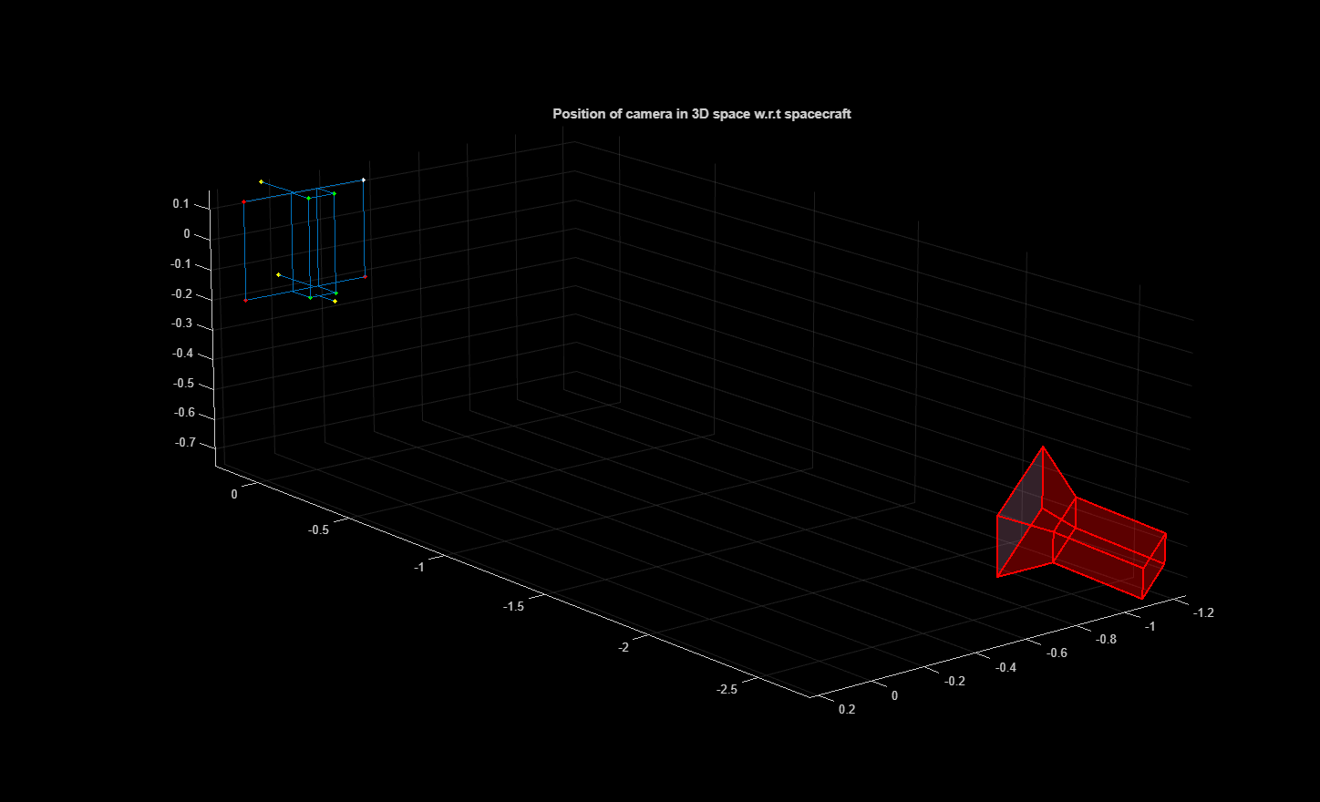
Plot a 3D scene representing the spacecraft and camera with its predicted orientation and position. Use the visualization to analyze the spatial relationship between the spacecraft and the camera.
pointsColorMap = [1 1 1; 1 0 0; 1 0 0; 1 0 0; 0 1 0; 0 1 0; 0 1 0; 0 1 0; 1 1 0; 1 1 0; 1 1 0];
h = pcshow(pointsSpeedCubeBodyRef,pointsColorMap,"VerticalAxis","Y","VerticalAxisDir","up","MarkerSize",100);
hold on
helperPlotSpacecraftWireframe(pointsSpeedCubeBodyRef);
plotCamera(size=0.15,AbsolutePose=worldPose);
axis equal;
hold off
set(gca,'View',[-129.1886   15.8252])
title("Position of camera in 3D space w.r.t spacecraft")
Convert the attitude and range from the spacecraft frame to the camera frame. The quaternion qPredictedCamera is a four-element vector representing the attitude of the spacecraft in the camera reference frame. The range rPredictedCamera is a 3-element vector representing the position of the spacecraft in the camera reference frame.
qPredictedCamera = dcm2quat(dcmPredictedSpacecraft')';
rPredictedCamera = dcmPredictedSpacecraft*(-rPredictedSpacecraft');
Compare the predicted quaternion data and range with the ground truth values to compute the angular error and positional error, respectively.
qGroundtruth = imgGroundTruth.q_vbs2tango_true{1};
rGroundtruth = imgGroundTruth.r_Vo2To_vbs_true{1};
qError = quatmultiply(quatconj(qPredictedCamera'),qGroundtruth);
degError = 2*atan2d(norm(qError(2:4)),qError(1));
if degError > 180
    degError = degError - 360;
end
rError = abs(norm(rPredictedCamera) - norm(rGroundtruth'));
Use the helperComputeAxisCoordinates helper function to compute the predicted and actual (ground truth) orientations and positions of a spacecraft as seen by a camera.
coordPredicted = helperComputeAxisCoordinates(cameraParamMatlab,qPredictedCamera',rPredictedCamera);
coordGroundtruth = helperComputeAxisCoordinates(cameraParamMatlab,qGroundtruth,rGroundtruth');
Display the predicted and the ground truth axis.
figure
imshow(img)
helperPlotSpacecraftAxes(coordPredicted,"r")
helperPlotSpacecraftAxes(coordGroundtruth,"g")
title("Spacecraft Image with Predicted (red color) vs ground truth Axis (green color)")
set(gca,'Position',[0 0 1 0.9])
text(10,80,['Angle Error: ', num2str(degError),' deg'],"Color",[0 1 0], "BackgroundColor", "k")
text(10,170,['Range Error: ', num2str(rError),' m'],"Color",[0 1 0], "BackgroundColor", "k")

Supporting Functions
helperCalculatePCK — Calculate the PCK of each predicted keypoint and corresponding ground truth keypoint.
function pckcurrent = helperCalculatePCK(pred,groundtruth,normalizationFactor,threshold)
assert(size(pred,1) == size(groundtruth,1) && size(pred,2) == size(groundtruth,2) && size(pred,3) == size(groundtruth,3))
pckcurrent = [];
for imgidx = 1:size(pred,3)
    pck = mean(sqrt((pred(:,1,imgidx)-groundtruth(:,1,imgidx)).^2+(pred(:,2,imgidx)-groundtruth(:,2,imgidx)).^2)./normalizationFactor<threshold);
    pckcurrent = [pckcurrent pck];
end
pckcurrent = mean(pckcurrent);
end
helperSpacecraftDatasetKeypointNames: returns the keypoint class names of spacecraft pose.
function classes = helperSpacecraftDatasetKeypointNames()
classes = ["1","2","3","4","5","6","7","8","9","10","11"]';
end
helperSpacecraftKeypointConnection: returns keypoint connection of spacecraft pose.
function connection = helperSpacecraftKeypointConnection()
connection = [1 2; 1 3; 2 4; 3 4; 5 6; 5 7; 6 8; 7 8];
end
helperCameraParametersCubesat: This function uses the provided camera properties to generate the camera parameters in MATLAB and OpenCV format
function  [cameraParamMatlab,intrinsicsOpenCV] = helperCameraParametersCubesat(cameraParameters)
intrinsicsOpenCV = cameraParameters.cameraMatrix;
distortionCoeff = cameraParameters.distCoeffs;
imageSize = [cameraParameters.Nu cameraParameters.Nv];
cameraParamMatlab = cameraIntrinsicsFromOpenCV(intrinsicsOpenCV,distortionCoeff,imageSize);
end
helperComputeAxisCoordinates: This function creates an x, y and z axis for the spacecraft in the world frame and uses the selected image's ground truth to project it to the camera frame.
function [pointsCameraPlane] = helperComputeAxisCoordinates(cameraParamMatlab,q,r)
points_axis = [0 0 0; 1 0 0; 0 1 0; 0 0 1];
dcm = quat2dcm(q);
pointsCameraPlane = (worldToImage(cameraParamMatlab,dcm,r,points_axis))';
pointsCameraPlane = [pointsCameraPlane(1,:),pointsCameraPlane(2,:)]';
end
helperPlotSpacecraftWireframe: plots a wireframe model of the spacecraft
function helperPlotSpacecraftWireframe(points)
plot3(points([1, 2, 4, 3, 1],1), points([1, 2, 4, 3, 1],2), points([1, 2, 4, 3, 1],3), Color = "#0072BD")
plot3(points([5, 6, 8, 7, 5],1), points([5, 6, 8, 7, 5],2), points([5, 6, 8, 7, 5],3), Color = "#0072BD")
plot3(points([8, 6, 2, 1, 8],1), points([8, 6, 6, 8, 8],2), points([8, 6, 6, 8, 8],3), Color = "#0072BD")
plot3(points([7, 5, 2, 1, 8],1), points([7, 5, 5, 7, 7],2), points([7, 5, 5, 7, 7],3), Color = "#0072BD")
plot3(points([9, 1],1), points([9, 9],2), points([9, 9],3), Color = "#0072BD")
plot3(points([10, 1],1), points([10, 10],2), points([10, 10],3), Color = "#0072BD")
plot3(points([11, 5],1), points([11, 11],2), points([11, 11],3), Color = "#0072BD")
end
helperPlotSpacecraftAxes: plots the selected image and it's spacecraft's corresponding x axis (red), y axis (green), z axis (blue).
function helperPlotSpacecraftAxes(pointCameraPlane,color)
x = pointCameraPlane(1:4);
y = pointCameraPlane(5:8);

hold on
quiver(x(1),y(1),x(2)-x(1),y(2)-y(1),color,"LineWidth",1)
quiver(x(1),y(1),x(3)-x(1),y(3)-y(1),color,"LineWidth",1)
quiver(x(1),y(1),x(4)-x(1),y(4)-y(1),color,"LineWidth",1)
hold off
end
helperDownloadDatasetAndDetectors — Download the pretrained spacecraft pose keypoint detector, spacecraft object detector and dataset.
function [pretrainedKeypointDetector,pretrainedObjectDetector,dataset] = helperDownloadDatasetAndDetectors(downloadFolder)
dataFilename = "SpacecraftDatasetAndModels.zip";
dataAndImageUrl = "https://ssd.mathworks.com/supportfiles/vision/data/" + dataFilename;
zipFile = fullfile(downloadFolder,dataFilename);
if ~exist(zipFile,"file")
    disp("Downloading training data and pretrained detectors (747 MB)...")
    websave(zipFile,dataAndImageUrl);
end
unzip(zipFile,downloadFolder)
dataset = fullfile(downloadFolder,"SpacecraftGroundTruth.mat");
pretrainedFolder = fullfile(downloadFolder,"PretrainedDetectors");
pretrainedKeypointDetector = fullfile(pretrainedFolder,"spacecraftHRNetKeypointDetector.mat");
pretrainedObjectDetector = fullfile(pretrainedFolder,"spacecraftYOLOv4Detector.mat");
end
See Also
trainHRNetObjectKeypointDetector | hrnetObjectKeypointDetector | trainingOptions (Deep Learning Toolbox) | estworldpose | plotCamera | yolov4ObjectDetector | insertShape | insertObjectKeypoints
References
[1] Ahmed, Z., Park, T.H., Bhattacharjee, A., Razel-Rezai, R., Graves, R., Saarela, O., Teramoto, R., Vemulapalli, K., and D'Amico, S. SPEED-UE-Cube: A Machine Learning Dataset for Autonomous, Vision-Based Spacecraft Navigation. 46th Rocky Mountain AAS Guidance, Navigation and Control Conference, Breckenridge, Colorado, February 2-7, 2024