Using the Multi-Camera Calibrator App
R2026bMulti-Camera Calibrator Overview
The Multi-Camera Calibrator app provides an interactive workflow for estimating the relative poses of two or more cameras simultaneously, helping minimize the potential error accumulation from sequential camera calibration. You can use the app to estimate the relative poses of cameras in systems with overlapping cameras, non‑overlapping cameras, or a mix of both, and to visually verify and refine calibration results before exporting them for use in your algorithms.
The app provides these convenient features:
Multiple calibration pattern support — Calibrate cameras using one of four commonly used calibration patterns: ChArUco board, AprilGrid, checkerboard, or circle grid.
Interactive pattern detection — Monitor detection progress while continuing to interact with the app. Restart or stop detection to adjust settings, rerun detection, or halt processing for large data sets before calibration proceeds.
Inspect and analyze detection results — Examine detected pattern points with visual overlays and status indicators, review image information, and identify problematic images before calibration.
Visualize reconstructed calibration scenes — Display the reconstructed 3-D calibration scene to evaluate camera poses, pattern coverage, and overall calibration quality.
Refine calibration accuracy — Analyze reprojection errors and improve calibration results by rejecting images or acquisitions that contribute excessive error.
To calibrate a single camera or a stereo pair, see Using the Single Camera Calibrator App or Using the Stereo Camera Calibrator App, respectively.
Use this process to calibrate a system of cameras, following best practices for preparing and capturing calibration images and evaluating accuracy.
Prepare and Capture Calibration Images — Ensure the cameras have been set up correctly and images have been captured clearly and consistently across all cameras.
Open the App — Open the app from the command line or from the Apps tab of the MATLAB® toolstrip.
Import Calibration Data — Import synchronized images from multiple cameras, from multiple cameras, along with the MAT file containing the intrinsic parameters for those cameras.
Detect Calibration Patterns and Inspect Results — Monitor detection progress, and visually inspect detection results.
Calibrate the Multi-Camera System — Perform, analyze, and refine calibration of the multi-camera system.
Export Calibration Results — Export the estimated parameters as a
multiCameraParametersobject.
Prepare and Capture Calibration Images
While you can perform multi-camera calibration with as few as 3 images per camera, for accurate multi‑camera calibration, capture 10–20 synchronized images per camera. Keep the relative positions and orientations of the cameras fixed, and ensure that at least one shared calibration pattern is visible to all cameras in each capture. Use uncompressed images or a lossless format such as PNG, and capture data from diverse viewpoints with motion across all rotational axes. Ensure that images are synchronized and free of motion blur. For detailed information on calibration image acquisition and the requirements that can affect calibration accuracy, see Data Collection Guidelines for Multi-Camera Calibration.
Organize your calibration data so that each camera has its own folder, and all folders contain matching image sets. This consistent naming ensures the system can correctly match and align images from different cameras during calibration.
Create one folder per camera (for example, given two cameras,
Camera-1andCamera-2).Place the images captured by each specific camera in the corresponding folder.
Verify that images that represent the same moment or scene across different cameras have exactly the same filename.
Open the App
MATLAB Toolstrip: On the Apps tab, in the Image Processing and Computer Vision section, click the Multi-Camera Calibrator icon.
MATLAB command prompt: Enter
multiCameraCalibrator.
Import Calibration Data
On the Calibrate tab of the app toolstrip, click Import. The app opens the Import dialog box to the Image and Intrinsics page, which contains a table you can use to import camera images and their corresponding MAT files.
Note
As a best practice, calibrate the intrinsic parameters of each camera using a data set other than the multi-camera calibration data set.
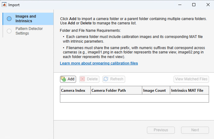
Images and Intrinsics — Select camera folders containing calibration images and the MAT file containing the intrinsic parameters. To enable the app to group images into acquisitions, corresponding images in each camera folder must have the same filename prefix and numeric index. For example, image001.png, image002.png, and image003.png must be present for each camera. You can select individual camera folders or a parent folder containing all camera folders.
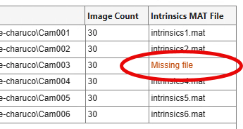
The app displays an empty cell for a missing image and reports an error for a missing MAT file. If images are missing, you can add them or proceed with only the available images. If a MAT file is missing, you must add it or remove the corresponding camera from the calibration process. You cannot select Next on this page until calibration data for all cameras has been successfully imported without errors.
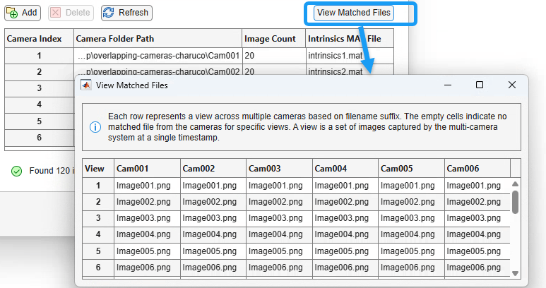
Display the matched images by clicking View Matched Files. Each row represents a single acquisition across multiple cameras, matched by filename suffix. An empty cell indicates that no image was found for that camera in that acquisition. An acquisition is a set of images captured simultaneously by the multi-camera system.
Pattern Detector Settings — Select the pattern type from the Choose Pattern drop-down menu, then specify the number of patterns. This value specifies the total number of calibration patterns of the selected type used in the data set. The available patterns are
ChArUco board,AprilGrid,Checkerboard, andAsymmetric Circle Grid. The default selection isChArUco board. The Pattern Detector Settings page provides these options for board measurements, pattern properties, and advanced settings for each type of board.board measurements, pattern properties, and advanced settings are defined as:
For detailed information about settings for ChArUco boards, see
detectCharucoBoardPoints.Option ChArUco Board Diagram Board Measurement:
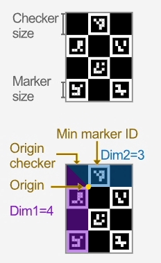
Checker size — Checker square side length in the units specified by Measurement units.
Marker size — ArUco marker side length in the units specified by Measurement units.
Measurement units — World measurement units, for example, mm, cm, m, in.
Pattern Properties:
Marker family — ArUco marker family.
Pattern dimensions [dim1, dim2] — Pattern dimensions of the board. With the origin square at the top-left corner of the board, dim1 is the number of squares in the vertical dimension, and dim2 is the number of squares in the horizontal dimension.
Minimum marker ID — Lowest marker ID in the pattern. Marker IDs must be sequential, in increments of 1. This increasing pattern ensures the detector only considers markers within the intended range and avoids false detections from other patterns in the scene.
Origin checker color — Color of the square in the top-left corner of the board, based on the defined orientation of the board. Select
BlackorWhite.
Advanced Settings:
Adaptive Thresholding Parameters
Window size range — Window size range used for adaptive thresholding, specified, in pixels, as a two-element vector of the form [min max].
Window size step — Window size step, in pixels, used for adaptive thresholding within the window size range.
Contour Filtering Parameters
Marker size range — Minimum and maximum size for the perimeter length of detected markers
Square tolerance — Maximum polygonal approximation error applied to each marker candidate. Decrease this value to filter false corner detections in occluded markers. Increase this value to detect marker candidates in highly distorted images.
Bit Extraction Arguments
Number of border bits — Number of border bits in the marker, specified as a positive integer. By default, the marker boundary contains one bit. If the function does not detect a marker candidate, first ensure that you have correctly set the Marker family, then check the ChArUco manufacturer manual to get the correct value for the number of border bits to use.
Decoder resolution per bit — Number of pixels per bit to use in the image obtained after correcting perspective distortion. Increase this value to improve the accuracy with which the function reads marker IDs at the expense of run-time speed.
Corner Refinement parameters
Enable corner refinement — Set this value to true to enable the subpixel refinement process for the detected marker corner locations. This step is computationally expensive. Enable this process only if the corner locations must be accurate for pose estimation or for camera calibration applications.
Refinement window size — Window size of the subpixel refinement process, in pixels. Increasing this value can cause the window area to include a corner of the image. As a result of this proximity, marker corners might move to incorrect locations.
Refinement maximum iterations — Maximum number of iterations for the subpixel refinement process. The process stops after the specified number of iterations, even if it has not achieved the termination tolerance set by Refinement tolerance.
Refinement tolerance — Termination tolerance for corner refinement.
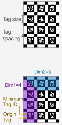
For detailed information about settings for AprilGrid, see
detectAprilGridPoints.Option AprilGrid Diagram Board Measurement:
Tag size — Length of one side of each AprilTag in the AprilGrid, specified in the units set by Measurement units.
Tag spacing — Space between AprilTags, specified in the units set by Measurement units selected.
Measurement units — World measurement units, for example, mm, cm, m, in.
Pattern Properties:
Tag family — AprilTag marker family.
Pattern dimensions — Pattern dimensions of the board. With the origin tag at the bottom-left corner of the grid, dim1 is the number of squares in the vertical dimension, and dim2 is the number of squares in the horizontal dimension.
Minimum tag ID — Lowest value tag ID in the AprilGrid pattern. The tags in the pattern must have sequential IDs with an increment of 1.
Number of border bits — Number of tag border bits, specified as
1or2. The tag border bits are used to generate the AprilTags. The border bits relate to each generated tag image, but not to a tag family. To set this value, refer to the manufacturer manual for your AprilTag pattern.
Advanced Settings:
Gaussian sigma — Standard deviation for the 2-D Gaussian smoothing kernel, specified as a nonnegative scalar. The Gaussian kernel smooths the input image to decrease white Gaussian noise. Increase this value to increase the processing speed, but at the cost of reduced precision.
Decimation factor — Decimation factor, specified as a positive integer. The decimation factor controls the scale of the downsampling. Increase this value to increase the detection rate, while decreasing detection distance.
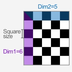
For detailed information about settings for checkerboard, see
detectCheckerboardPoints.Option Checkerboard Diagram Board Measurement:
Square size — Measurement of one side of a checkerboard square.
Pattern Properties:
Pattern dimensions — The number of checkerboard squares in dimension 1, the vertical direction, and dimension 2, the horizontal direction.
Advanced Settings:
Image distortion — Select
Lowwhen the images do not contain a high level of distortion. SelectHighwhen the images contain a high level of distortion, which is typical of a wide field of view camera, such as a fisheye camera.Minimum corner metric — Decrease this value to detect blurry keypoints in images. Increase this value to reduce the number of false corner detections, or for high quality points. Set to
Autofor the app to adjust the value according to the Image distortion value.
For detailed information about settings for Asymmetric Circle Grid, see
detectCircleGridPoints.Option Asymmetric Circle Grid Diagram Board Measurement
Center-to-center distance — Center-to-center distance between two adjacent circles.
Pattern Properties
Pattern dimensions — Number of circles in each row and column of the pattern, specified as a two-element vector [dim1 dim2], where dim1 and dim2 are the number of circles in the x- and y-dimensions, respectively. The origin is at the center of the top-left circle.
Circle color — Select
BlackorWhite, based on which has the stronger contrast with the background.

Detect Calibration Patterns and Inspect Results
In the Pattern section of the app toolstrip, select Detect Pattern to begin detecting patterns in the imported images. The app indicates whether a pattern is detected for each image and updates results as detection proceeds. During detection, the app displays a progress bar, and you can view and zoom images, enabling you to monitor progress and visually inspect results in real-time. Once patterns have been detected successfully, the Calibrate button becomes active.
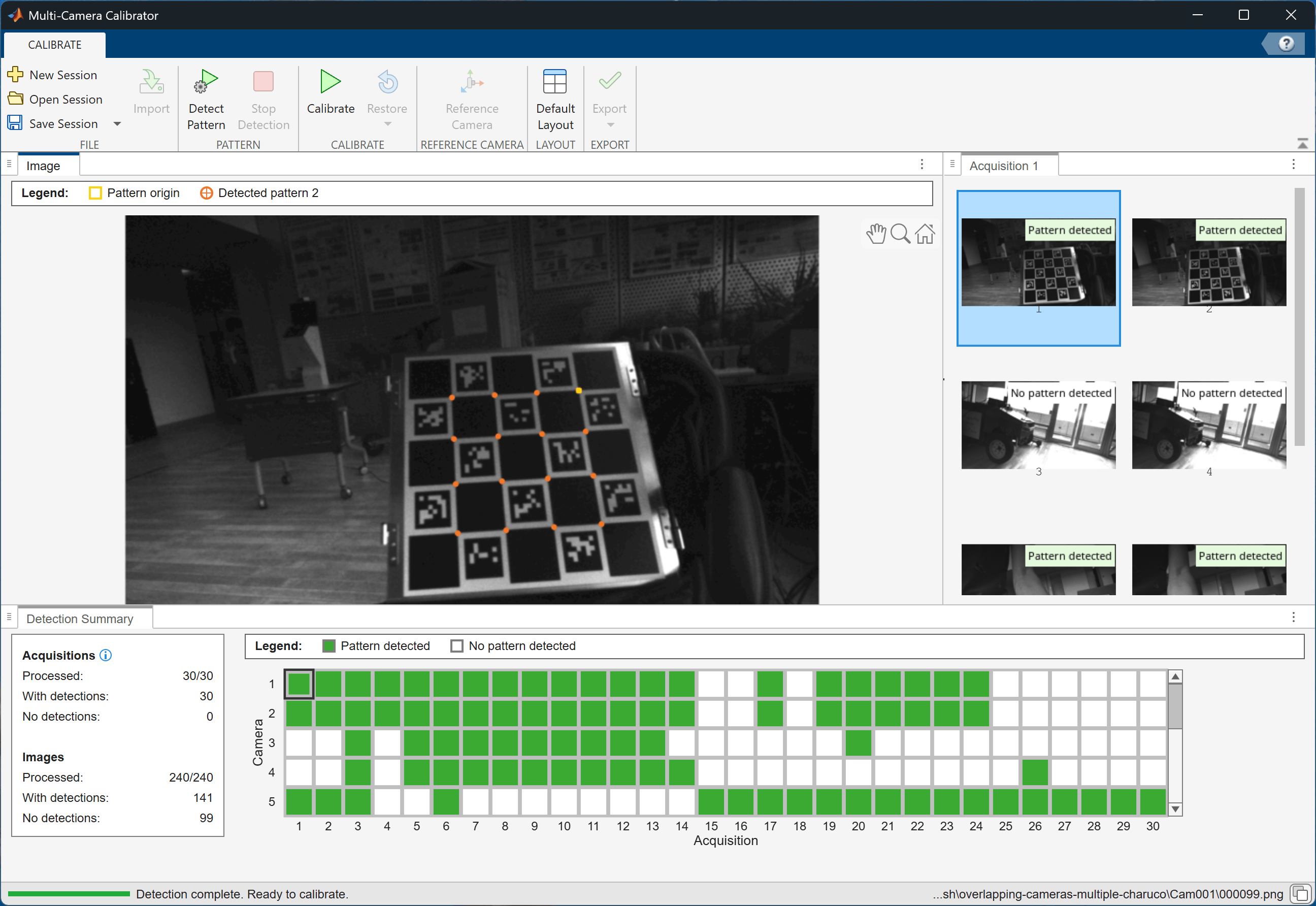
If the app returns an error, or if it does not consistently detect patterns across the data set, stop detection by selecting Stop Detection. Then, click the Detect Pattern button in the toolstrip to verify the pattern detector settings. Adjust the detector parameters as needed before running detection again.
Calibrate the Multi-Camera System
To estimate the relative poses of all the cameras, click Calibrate. The app displays calibration progress and reports results when complete.
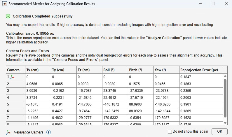
After calibration completes, the app displays a summary of the calibration results, including the mean reprojection error for the data set and the estimated pose and reprojection error of each camera relative to the reference camera. Use this information to evaluate calibration quality. If necessary, refine the calibration by excluding images that contribute large reprojection errors and then recalibrate. If you select Do not show this again, the app does not display a summary after future calibration sessions, but you can view it on the Camera Poses and Errors tab.
Analyze and Refine Calibration Results
Use the Analyze Calibration pane to evaluate calibration quality and identify images or acquisitions that might be contributing to high reprojection errors.
The color-coded grid displays the reprojection error for each image or acquisition. Colors indicate the relative magnitude of the reprojection error, helping you quickly identify data that might be reducing calibration accuracy. The grid also indicates excluded images and images in which no calibration pattern was detected.
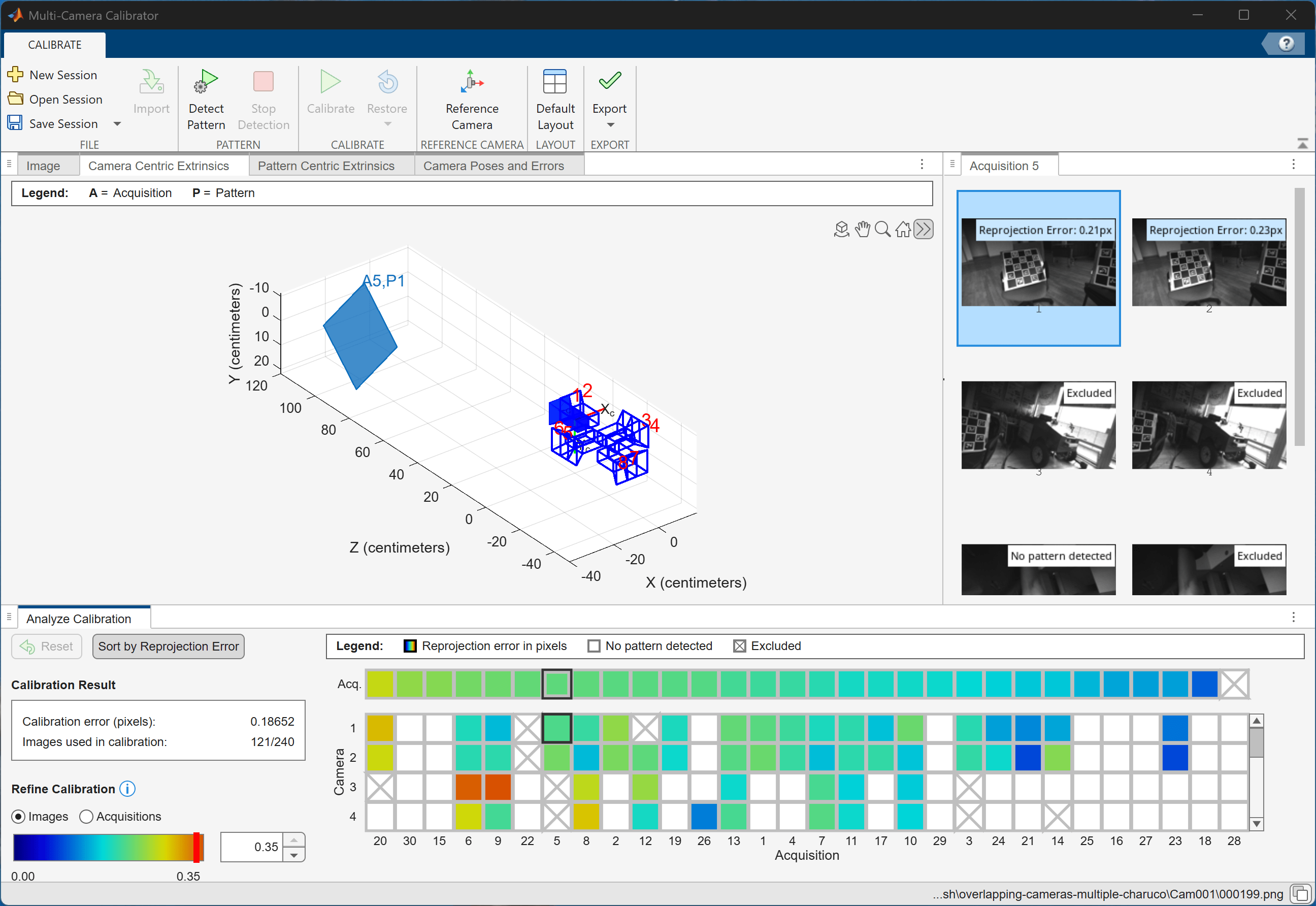
To investigate and refine calibration results:
Review the Calibration Result section to assess the overall calibration error and the number of images used in calibration.
Select Images or Acquisitions in the Refine Calibration section to analyze reprojection errors at the image or acquisition level.
Sort images or acquisitions by reprojection error to identify the largest contributors to calibration error.
Exclude outliers by setting a reprojection error threshold, or interactively exclude individual images or acquisitions from the calibration.
Select images or acquisitions in the reprojection error grid to view the corresponding images and error values.
Use the 3-D visualization to inspect the estimated camera poses and calibration pattern locations. You can rotate, pan, and zoom the scene using a mouse or the navigation toolbar to examine the calibration results from different viewpoints, and use the Home button to restore the default view.
Examine the reconstructed calibration scene from multiple viewpoints to verify the estimated camera arrangement and identify potential calibration issues.
Click Calibrate to rerun calibration using the refined data set. The app reuses the existing detection results, so you do not need to repeat pattern detection.
Compare the calibration error before and after recalibration to determine whether the refinement improved the results. Use the Restore button to return to a previous calibration result or the initial calibration result.
Select one or more image or acquisition cells in the reprojection error grid to visualize the corresponding calibration scenes. Use Ctrl+Click or Ctrl+Arrow keys to select multiple cells and compare scenes, or press Ctrl+A to display all scenes.
Tip
For large data sets, begin by excluding entire acquisitions with high reprojection errors to remove major outliers. Then, refine the calibration further by excluding individual images as needed to improve accuracy.
To review or change the reference camera properties, select Reference Camera in the Reference Camera section of the app toolstrip.
Reference Camera Properties dialog box enables you to define the coordinate system used to display and export calibration results. Select a camera and specify its pose using either a transformation from the MATLAB workspace or a custom homogeneous transformation matrix. The app updates the reported camera poses and 3-D visualization accordingly. Changing the reference camera does not affect the calibration results. It changes only the coordinate system used to represent the estimated extrinsic parameters.
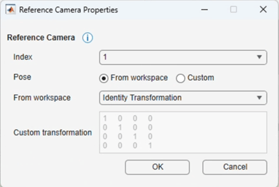
Index — Select the camera to use as the reference camera.
Pose — Specify how to define the reference camera pose.
From workspace — Select a transformation from the MATLAB workspace.
Custom — Specify a custom 4-by-4 homogeneous transformation matrix.
From workspace — Select the transformation to apply to the reference camera.
Custom transformation — Specify a 4-by-4 homogeneous transformation matrix that defines the reference camera pose. The app applies this matrix when you set Pose to Custom.
Export Calibration Results
Under Export, select Export
Parameters to Workspace to create a multiCameraParameters object in the MATLAB workspace. The object contains the estimated intrinsic and extrinsic parameters
for all calibrated cameras. You can use this object for multi-camera computer vision
workflows, such as 3-D motion reconstruction, multi-camera multi-object tracking, and
multi-sensor calibration.
Under Export, select Generate MATLAB Script to create a MATLAB script that reproduces the calibration workflow and saves the estimated parameters. You can use the generated script to rerun the calibration with the same settings or modify the workflow programmatically.
See Also
Apps
Functions
estimateMultiCameraParameters|detectMultiPatternPoints|detectPatternPoints|patternWorldPoints|showExtrinsics|showReprojectionErrors|plotCamera|estimateCameraParameters|undistortImage

