使用深度学习增加图像分辨率
此示例说明如何使用超深超分辨率 (VDSR) 神经网络从低分辨率图像创建高分辨率图像。
超分辨率是从低分辨率图像创建高分辨率图像的过程。此示例采用单图像超分辨率 (SISR),其目标是从一个低分辨率图像恢复一个高分辨率图像。SISR 具有挑战性,因为通常无法从低分辨率图像恢复高频图像成分。如果没有高频信息,得到的高分辨率图像的质量是有限的。此外,SISR 是一个不适定问题,因为一个低分辨率图像可以产生若干种可能的高分辨率图像。
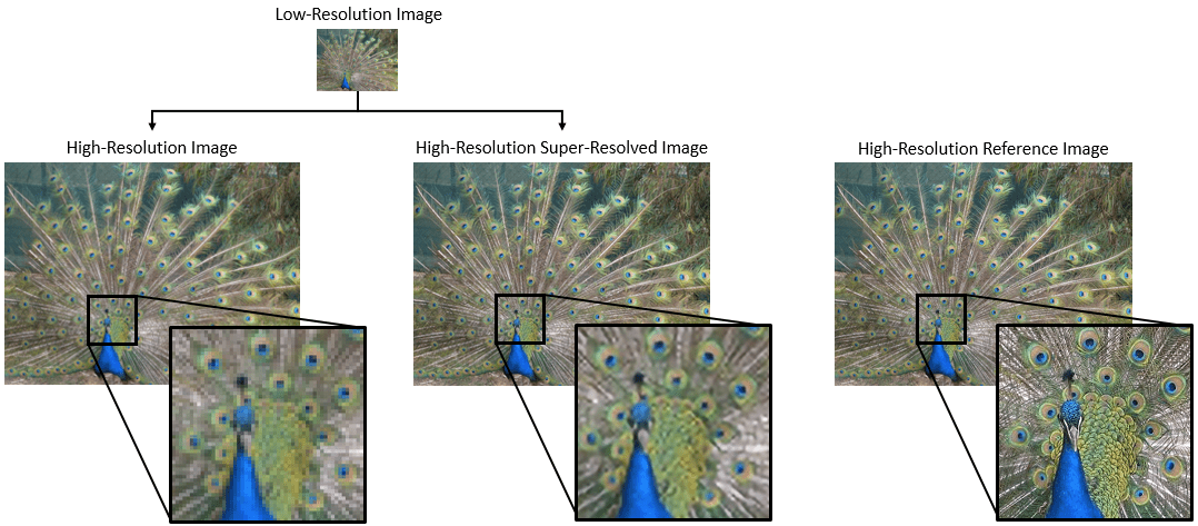
目前已提出包括深度学习算法在内的几种方法来执行 SISR。此示例探索了一种适用于 SISR 的深度学习算法,称为超深超分辨率 (VDSR) [1]。
VDSR 网络
VDSR 是一种用于执行单图像超分辨率 [1] 的卷积神经网络架构。VDSR 网络学习低分辨率图像和高分辨率图像之间的映射。这种映射是有可能获得的,因为低分辨率图像和高分辨率图像具有相似的图像成分,主要区别在于高频细节。
VDSR 采用一种残差学习策略,这意味着网络会学习估计残差图像。在超分辨率上下文中,残差图像是高分辨率参考图像和低分辨率图像之间的差异,低分辨率图像已使用双三次插值扩增以匹配参考图像的大小。残差图像包含关于图像高频细节的信息。
VDSR 网络基于彩色图像的亮度检测残差图像。图像的亮度通道 Y 通过红色、绿色和蓝色像素值的线性组合来表示每个像素的亮度。而图像的两个色度通道 Cb 和 Cr 使用红色、绿色和蓝色像素值的不同线性组合来表示色差信息。VDSR 仅使用亮度通道进行训练,因为人类对亮度变化的感知比对颜色变化更敏感。

如果 是高分辨率图像的亮度, 是使用双三次插值扩增的低分辨率图像的亮度,则 VDSR 网络的输入是 ,网络学习基于训练数据预测 。
在 VDSR 网络学习估计残差图像后,您可以将估计的残差图像添加到上采样的低分辨率图像中,然后将图像转换回 RGB 颜色空间,从而重构高分辨率图像。
参考图像大小与低分辨率图像大小的关系可通过缩放因子来表示。随着缩放因子的增大,SISR 变得更加不适定,因为低分辨率图像会丢失有关高频图像成分的更多信息。VDSR 通过使用大感受野来解决此问题。此示例使用缩放增强来训练具有多缩放因子的 VDSR 网络。缩放增强可以改进在较大缩放因子下的结果,因为网络可以利用较小缩放因子下的图像上下文。此外,VDSR 网络可以泛化至接受具有非整数缩放因子的图像。
下载训练和测试数据
下载包含 20,000 个静态自然图像的 IAPR TC-12 Benchmark [2]。该数据集包括人、动物、城市等的照片。数据文件的大小约为 1.8 GB。如果您不想下载训练数据集,则可以通过在命令行中键入 load("trainedVDSRNet_v2.mat"); 来加载预训练的 VDSR 网络。然后,直接转至本示例中的使用 VDSR 网络执行单图像超分辨率部分。
使用辅助函数 downloadIAPRTC12Data 下载数据。此函数作为支持文件包含在本示例中。指定 dataDir 作为数据的存放位置。
dataDir = tempdir;
downloadIAPRTC12Data(dataDir);
tempdir;
downloadIAPRTC12Data(dataDir);此示例将使用 IAPR TC-12 Benchmark 数据的一个小型子集来训练网络。加载 imageCLEF 训练数据。所有图像均为 32 位 JPEG 彩色图像。
trainImagesDir = fullfile(dataDir,"iaprtc12","images","02");
exts = [".jpg",".bmp",".png"];
pristineImages = imageDatastore(trainImagesDir,FileExtensions=exts);
列出训练图像数。
numel(pristineImages.Files)
ans = 616
准备训练数据
要创建训练数据集,请生成由上采样图像和对应残差图像组成的图像对。
上采样图像以 MAT 文件形式存储在磁盘的 upsampledDirName 目录中。计算出的表示网络响应的残差图像以 MAT 文件形式存储在磁盘的 residualDirName 目录中。这些 MAT 文件以 double 数据类型存储,以在训练网络时实现更高的精确度。
upsampledDirName = trainImagesDir+filesep+"upsampledImages";
residualDirName = trainImagesDir+filesep+"residualImages";
使用辅助函数 createVDSRTrainingSet 对训练数据进行预处理。此函数作为支持文件包含在本示例中。
该辅助函数对 trainImages 中的每个原始图像执行以下操作:
将图像转换为 YCbCr 颜色空间
以不同缩放因子缩小亮度 (Y) 通道,以创建低分辨率样本图像,然后使用双三次插值将图像大小调整为原始大小
计算原始图像和调整大小后的图像之间的差异。
将调整大小后的图像和残差图像保存到磁盘。
scaleFactors = [2 3 4];
createVDSRTrainingSet(pristineImages,scaleFactors,upsampledDirName,residualDirName);
定义训练集的预处理管道
在此示例中,网络输入是使用双三次插值进行上采样后的低分辨率图像。所需的网络响应是残差图像。基于输入图像文件集合创建一个名为 upsampledImages 的图像数据存储。基于计算出的残差图像文件集合创建一个名为 residualImages 的图像数据存储。两个数据存储都需要使用辅助函数 matRead 从图像文件中读取图像数据。此函数作为支持文件包含在本示例中。
upsampledImages = imageDatastore(upsampledDirName,FileExtensions=".mat",ReadFcn=@matRead);
residualImages = imageDatastore(residualDirName,FileExtensions=".mat",ReadFcn=@matRead);
创建一个指定数据增强参数的 imageDataAugmenter。在训练期间使用数据增强来更改训练数据,这可以有效地增加可用的训练数据量。此处,增强器指定 90 度的随机旋转和 x 方向上的随机翻转。
augmenter = imageDataAugmenter( ...
    RandRotatio=@()randi([0,1],1)*90, ...
    RandXReflection=true);
创建一个 randomPatchExtractionDatastore (Image Processing Toolbox) 以根据上采样图像和残差图像数据存储执行随机补片提取。补片提取是从单个较大图像中提取大量小图像补片或图块的过程。这种类型的数据增强经常用于图像到图像回归问题,其中许多网络架构可以基于非常小的输入图像大小进行训练。这意味着可以从原始训练集中的每个全大小图像中提取大量补片,这极大地增加了训练集的大小。
patchSize = [41 41];
patchesPerImage = 64;
dsTrain = randomPatchExtractionDatastore(upsampledImages,residualImages,patchSize, ...
    DataAugmentation=augmenter,PatchesPerImage=patchesPerImage);
生成的数据存储 dsTrain 在一轮训练的每次迭代中向网络提供小批量数据。预览从数据存储中读取的结果。
inputBatch = preview(dsTrain);
disp(inputBatch)
      InputImage      ResponseImage
    ______________    ______________

    {41×41 double}    {41×41 double}
    {41×41 double}    {41×41 double}
    {41×41 double}    {41×41 double}
    {41×41 double}    {41×41 double}
    {41×41 double}    {41×41 double}
    {41×41 double}    {41×41 double}
    {41×41 double}    {41×41 double}
    {41×41 double}    {41×41 double}
设置 VDSR 层
此示例使用 Deep Learning Toolbox™ 中的 40 个单独层定义 VDSR 网络,这些层包括:
imageInputLayer- 图像输入层convolution2dLayer- 卷积神经网络的二维卷积层reluLayer- 修正线性单元 (ReLU) 层
第一个层,即 imageInputLayer,对图像补片进行操作。补片大小基于网络感受野,它是一个空间图像区域,影响网络中最顶层的响应。理想情况下,网络感受野与图像大小相同,这样感受野可以看到图像中的所有高级特征。在这种情况下,对于具有 D 个卷积层的网络,感受野是 (2D+1)×(2D+1)。
VDSR 有 20 个卷积层,因此感受野和图像补片大小为 41×41。图像输入层接受具有一个通道的图像,因为仅使用亮度通道训练 VDSR。
networkDepth = 20;
firstLayer = imageInputLayer([41 41 1],Name="InputLayer",Normalization="none");
图像输入层后跟一个二维卷积层,其中包含 64 个大小为 3×3 的滤波器。小批量大小决定滤波器的数量。对每个卷积层的输入填零,使特征图与每次卷积后的输入始终大小相同。He 的方法 [3] 将权重初始化为随机值,以在神经元学习中引入不对称性。每个卷积层后跟一个 ReLU 层,该层在网络中引入非线性。
convLayer = convolution2dLayer(3,64,Padding=1, ...
    WeightsInitializer="he",BiasInitializer="zeros",Name="Conv1");
指定一个 ReLU 层。
relLayer = reluLayer(Name="ReLU1");中间各层包含 18 个交替的卷积层和修正线性单元层。每个卷积层包含 64 个大小为 3×3×64 的滤波器,每个滤波器对 64 个通道中的 3×3 空间区域进行操作。如前所述,每个卷积层都后跟一个 ReLU 层。
middleLayers = [convLayer relLayer];
for layerNumber = 2:networkDepth-1
    convLayer = convolution2dLayer(3,64,Padding=[1 1], ...
        WeightsInitializer="he",BiasInitializer="zeros", ...
        Name="Conv"+num2str(layerNumber));

    relLayer = reluLayer(Name="ReLU"+num2str(layerNumber));
    middleLayers = [middleLayers convLayer relLayer];
end
最终层是一个卷积层,该层具有一个大小为 3×3×64 的滤波器,用于重构图像。
finalLayer = convolution2dLayer(3,1,Padding=[1 1], ...
    WeightsInitializer="he",BiasInitializer="zeros", ...
    NumChannels=64,Name="Conv"+num2str(networkDepth));
串联所有层以形成 VDSR 网络。
layers = [firstLayer middleLayers finalLayer];
基于层数组创建一个 dlnetwork 对象。
net = dlnetwork(layers);
指定训练选项
使用具有动量的随机梯度下降 (SGDM) 优化来训练网络。使用 trainingOptions 函数指定 SGDM 的超参数设置。学习率最初为 0.1,每 10 轮降低为原来的十分之一。进行 100 轮训练。
训练深度网络很耗时。通过指定高学习率可加快训练速度。然而,这可能会导致网络的梯度爆炸或不受控制地增长,阻碍网络训练成功。要将梯度保持在有意义的范围内,请通过将 "GradientThreshold" 指定为 0.01 来启用梯度裁剪,并指定 "GradientThresholdMethod" 使用梯度的 L2-范数。
maxEpochs = 100;
epochIntervals = 1;
initLearningRate = 0.1;
learningRateFactor = 0.1;
l2reg = 0.0001;
miniBatchSize = 64;
options = trainingOptions("sgdm", ...
    Momentum=0.9, ...
    InitialLearnRate=initLearningRate, ...
    LearnRateSchedule="piecewise", ...
    LearnRateDropPeriod=10, ...
    LearnRateDropFactor=learningRateFactor, ...
    L2Regularization=l2reg, ...
    MaxEpochs=maxEpochs, ...
    MiniBatchSize=miniBatchSize, ...
    GradientThresholdMethod="l2norm", ...
    GradientThreshold=0.01, ...
    Plots="training-progress", ...
    Verbose=true);
训练网络
默认情况下,该示例加载 VDSR 网络的一个预训练版本,该版本已对超分辨率图像进行缩放因子为 2、3 和 4 的训练。借助预训练网络,您无需等待训练完成,即可执行测试图像的超分辨率处理。
使用 trainnet 函数训练神经网络。对于回归,请使用均方误差损失。默认情况下,trainnet 函数使用 GPU(如果有)。在 GPU 上进行训练需要 Parallel Computing Toolbox™ 许可证和受支持的 GPU 设备。有关受支持设备的信息,请参阅GPU 计算要求 (Parallel Computing Toolbox)。否则,trainnet 函数使用 CPU。要指定执行环境,请使用 ExecutionEnvironment 训练选项。
在 NVIDIA Titan X GPU 上训练大约需要 6 个小时。
doTraining =false; if doTraining net = trainnet(dsTrain,net,"mse",options); modelDateTime = string(datetime("now",Format="yyyy-MM-dd-HH-mm-ss")); save("trainedVDSR-"+modelDateTime+".mat","net"); else load("trainedVDSRNet_v2.mat"); end
使用 VDSR 网络执行单图像超分辨率
要使用 VDSR 网络执行单图像超分辨率 (SISR),请按照此示例的后续步骤进行操作:
基于高分辨率参考图像创建一个示例低分辨率图像。
使用双三次插值对该低分辨率图像执行 SISR,双三次插值是一种不依赖于深度学习的传统图像处理解决方案。
使用 VDSR 神经网络对该低分辨率图像执行 SISR。
以可视化方式比较使用双三次插值和 VDSR 重构的高分辨率图像。
量化超分辨率图像与高分辨率参考图像的相似性,以此评估超分辨率图像的质量。
创建示例低分辨率图像
测试数据集 testImages 包含 Image Processing Toolbox™ 中提供的 20 个未畸变图像。将图像加载到 imageDatastore 中,并以蒙太奇方式显示图像。
fileNames = ["sherlock.jpg","peacock.jpg","fabric.png","greens.jpg", ...
    "hands1.jpg","kobi.png","lighthouse.png","office_4.jpg", ...
    "onion.png","pears.png","yellowlily.jpg","indiancorn.jpg", ...
    "flamingos.jpg","sevilla.jpg","llama.jpg","parkavenue.jpg", ...
    "strawberries.jpg","trailer.jpg","wagon.jpg","football.jpg"];
filePath = fullfile(matlabroot,"toolbox","images","imdata")+filesep;
filePathNames = strcat(filePath,fileNames);
testImages = imageDatastore(filePathNames);
以蒙太奇方式显示测试图像。
montage(testImages)

选择一个测试图像用于测试超分辨率网络。
testImage ="sherlock.jpg"; Ireference = imread(testImage); Ireference = im2double(Ireference); imshow(Ireference) title("High-Resolution Reference Image")
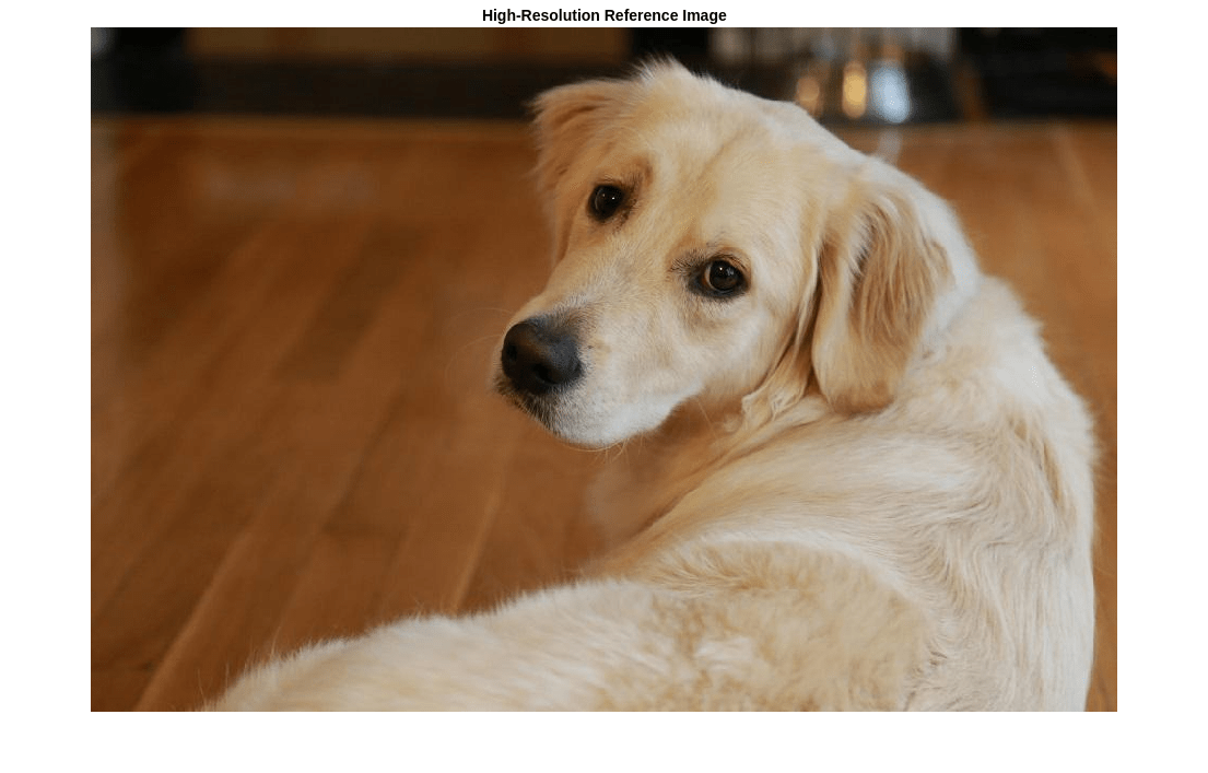
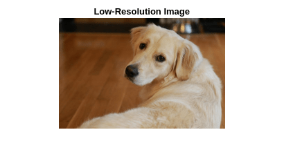
使用 imresize 和缩放因子 0.25 创建高分辨率参考图像的一个低分辨率版本。图像的高频分量在缩减分辨率过程中丢失。
scaleFactor = 0.25;
Ilowres = imresize(Ireference,scaleFactor,"bicubic");
imshow(Ilowres)
title("Low-Resolution Image")
使用双三次插值提高图像分辨率
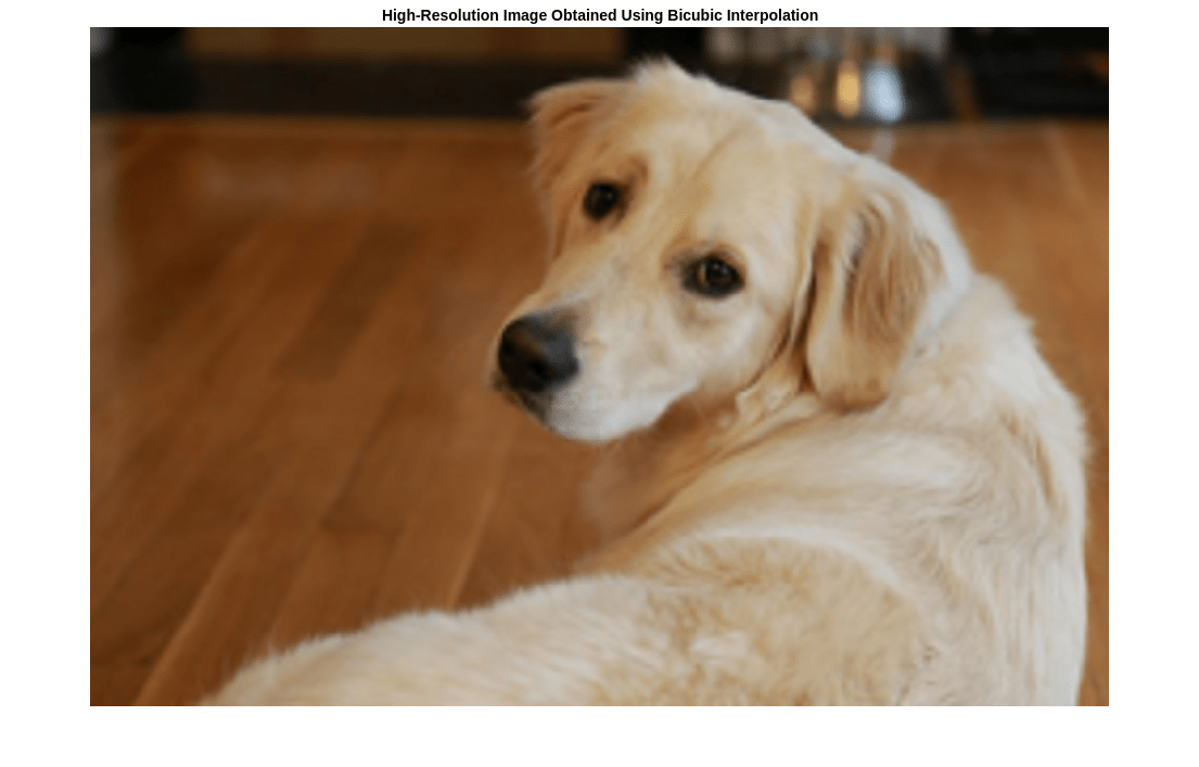
不借助深度学习来提高图像分辨率的一种标准方法是使用双三次插值。使用双三次插值扩增低分辨率图像,使所得高分辨率图像与参考图像大小相同。
[nrows,ncols,np] = size(Ireference);
Ibicubic = imresize(Ilowres,[nrows ncols],"bicubic");
imshow(Ibicubic)
title("High-Resolution Image Obtained Using Bicubic Interpolation")
使用 VDSR 网络提高图像分辨率
如前文所述,VDSR 只使用图像的亮度通道进行训练,因为人类对亮度变化的感知比对颜色变化更敏感。
使用 rgb2ycbcr (Image Processing Toolbox) 函数将低分辨率图像从 RGB 颜色空间转换为亮度 (Iy) 和色度(Icb 和 Icr)通道。
Iycbcr = rgb2ycbcr(Ilowres);
Iy = Iycbcr(:,:,1);
Icb = Iycbcr(:,:,2);
Icr = Iycbcr(:,:,3);
使用双三次插值扩增亮度通道和两个色度通道。上采样的色度通道 Icb_bicubic 和 Icr_bicubic 不需要进一步处理。
Iy_bicubic = imresize(Iy,[nrows ncols],"bicubic");
Icb_bicubic = imresize(Icb,[nrows ncols],"bicubic");
Icr_bicubic = imresize(Icr,[nrows ncols],"bicubic");
对扩增的亮度分量 Iy_bicubic 应用经过训练的 VDSR 网络。观察最终层的激活值。网络的输出是所需的残差图像。
Iresidual = predict(net,Iy_bicubic);
Iresidual = double(Iresidual);
imshow(Iresidual,[])
title("Residual Image from VDSR")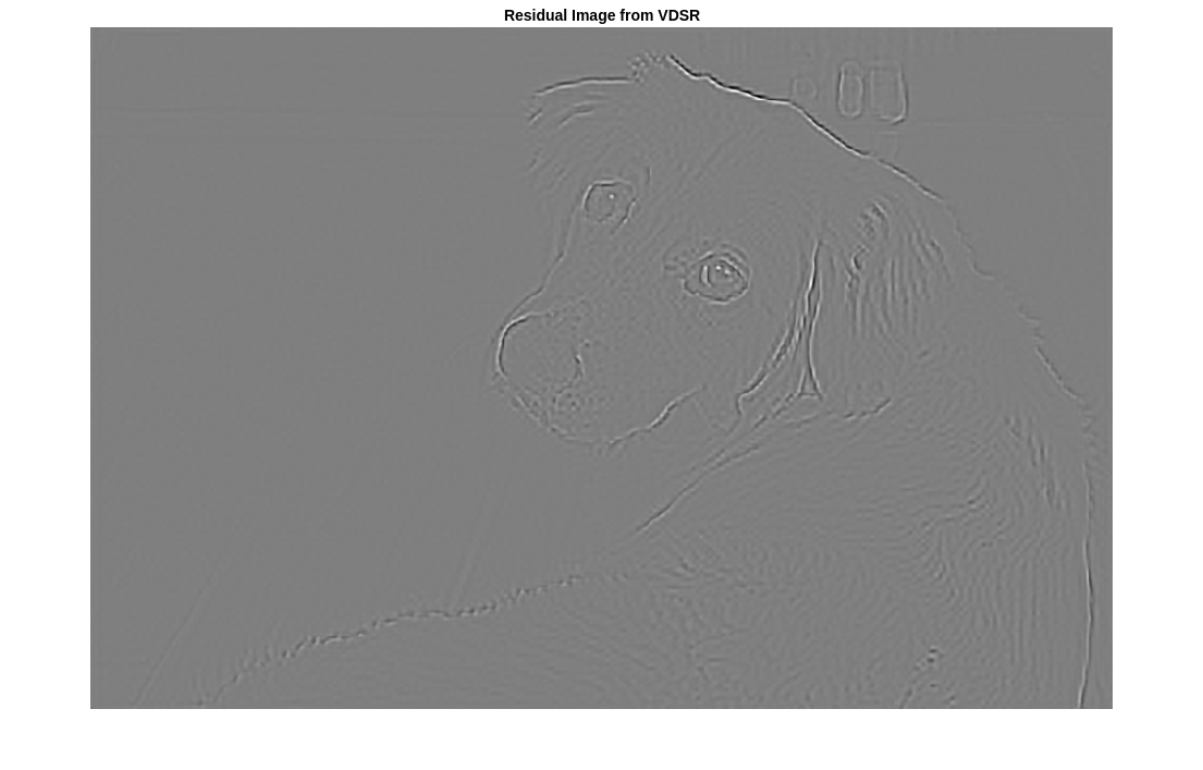
将残差图像添加到扩增的亮度分量中,得到高分辨率 VDSR 亮度分量。
Isr = Iy_bicubic + Iresidual;
将高分辨率 VDSR 亮度分量与扩增的颜色分量串联起来。使用 ycbcr2rgb (Image Processing Toolbox) 函数将图像转换为 RGB 颜色空间。结果为使用 VDSR 的最终高分辨率彩色图像。
Ivdsr = ycbcr2rgb(cat(3,Isr,Icb_bicubic,Icr_bicubic));
imshow(Ivdsr)
title("High-Resolution Image Obtained Using VDSR")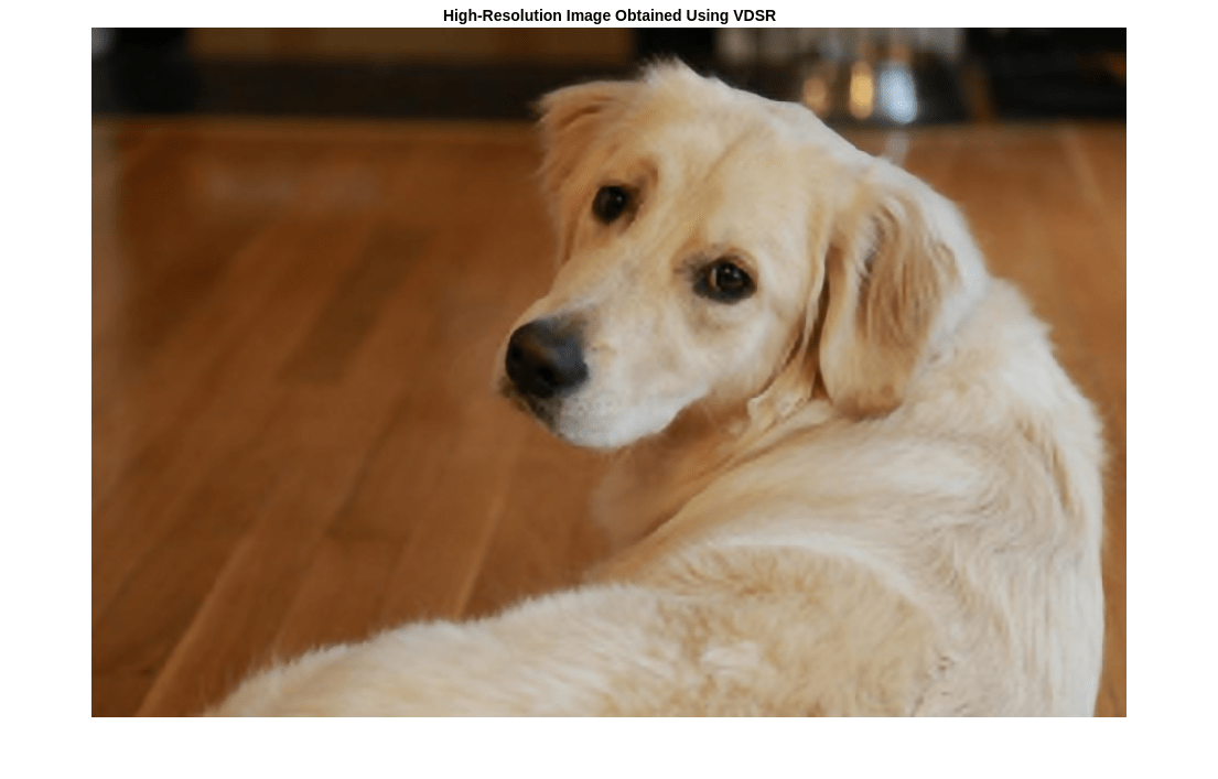
可视化和定量比较
为了在视觉上更好地理解高分辨率图像,请检查每个图像中的一个小区域。使用向量 roi 指定感兴趣的区域 (ROI),格式为 [x y 宽度 高度]。其中的元素定义了 ROI 左上角的 x 和 y 坐标,以及它的宽度和高度。
roi = [360 50 400 350];
将高分辨率图像裁剪到此 ROI,并以蒙太奇方式显示结果。与使用双三次插值创建的高分辨率图像相比,VDSR 图像具有更清晰的细节和更锐利的边缘。
montage({imcrop(Ibicubic,roi),imcrop(Ivdsr,roi)})
title("High-Resolution Results Using Bicubic Interpolation (Left) vs. VDSR (Right)");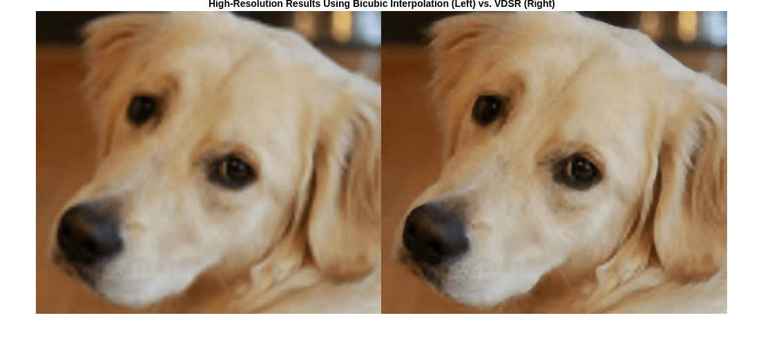
使用图像质量度量来定量比较使用双三次插值的高分辨率图像和 VDSR 图像。参考图像是准备低分辨率图像示例时所用的原始高分辨率图像 Ireference。
对照参考图像测量每个图像的峰值信噪比 (PSNR)。PSNR 值越大,通常表示图像质量越好。有关该度量的详细信息,请参阅 psnr (Image Processing Toolbox)。
bicubicPSNR = psnr(Ibicubic,Ireference)
bicubicPSNR = 38.4747
vdsrPSNR = psnr(Ivdsr,Ireference)
vdsrPSNR = 39.2346
测量每个图像的结构相似性指数 (SSIM)。SSIM 对照参考图像评估图像的以下三个特征的视觉效果:亮度、对比度和结构。SSIM 值越接近 1,测试图像与参考图像越一致。有关该度量的详细信息,请参阅 ssim (Image Processing Toolbox)。
bicubicSSIM = ssim(Ibicubic,Ireference)
bicubicSSIM = 0.9861
vdsrSSIM = ssim(Ivdsr,Ireference)
vdsrSSIM = 0.9874
使用自然图像质量评估方法 (NIQE) 测量图像感知质量。NIQE 分数越小,表示感知质量越好。有关该度量的详细信息,请参阅 niqe (Image Processing Toolbox)。
bicubicNIQE = niqe(Ibicubic)
bicubicNIQE = 5.1721
vdsrNIQE = niqe(Ivdsr)
vdsrNIQE = 4.7610
分别计算缩放因子为 2、3 和 4 时整个测试图像集的平均 PSNR 和 SSIM。为简单起见,您可以使用辅助函数 vdsrMetrics 来计算平均度量。此函数作为支持文件包含在本示例中。
scaleFactors = [2 3 4];
vdsrMetrics(net,testImages,scaleFactors);
Results for Scale factor 2

Average PSNR for Bicubic = 31.467070
Average PSNR for VDSR = 31.481973
Average SSIM for Bicubic = 0.935820
Average SSIM for VDSR = 0.947057

Results for Scale factor 3

Average PSNR for Bicubic = 28.107057
Average PSNR for VDSR = 28.430546
Average SSIM for Bicubic = 0.883927
Average SSIM for VDSR = 0.894634

Results for Scale factor 4

Average PSNR for Bicubic = 27.066129
Average PSNR for VDSR = 27.846590
Average SSIM for Bicubic = 0.863270
Average SSIM for VDSR = 0.878101
对于每个缩放因子,VDSR 都具有比双三次插值更好的度量分数。
参考资料
[1] Kim, J., J. K. Lee, and K. M. Lee."Accurate Image Super-Resolution Using Very Deep Convolutional Networks."Proceedings of the IEEE® Conference on Computer Vision and Pattern Recognition.2016, pp. 1646-1654.
[2] Grubinger, M., P. Clough, H. Müller, and T. Deselaers."The IAPR TC-12 Benchmark:A New Evaluation Resource for Visual Information Systems."Proceedings of the OntoImage 2006 Language Resources For Content-Based Image Retrieval.Genoa, Italy.Vol. 5, May 2006, p. 10.
[3] He, K., X. Zhang, S. Ren, and J. Sun."Delving Deep into Rectifiers:Surpassing Human-Level Performance on ImageNet Classification."Proceedings of the IEEE International Conference on Computer Vision, 2015, pp. 1026-1034.
另请参阅
trainnet | predict | trainingOptions | dlnetwork | imageDatastore | randomPatchExtractionDatastore (Image Processing Toolbox)
主题
- Datastores for Deep Learning
- 预处理图像以进行深度学习
- 深度学习层列表
- Increase Image Resolution Using VDSR Network Running on FPGA (Deep Learning HDL Toolbox)