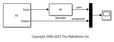
Idmodel
Simulate identified linear model in Simulink software
Libraries:
System Identification Toolbox /
Models
Description
The Idmodel block simulates the output of an identified linear model
using time-domain input data. The model is a state-space (idss
),
linear grey-box (idgrey
), polynomial (idpoly
),
transfer function (idtf
), or process (idproc
)
model that you previously estimated or created. For the simulation of state-space and
linear grey-box models, you can specify the initial state values. For other linear
models, specify initial conditions using an initialCondition
object.
You can also add noise to the simulated output.
Examples
Simulate Identified Linear Model in Simulink with Initial Conditions
Set the initial states for simulating a linear model such that the simulation provides a best fit to measured input-output data.
Ports
Input
Port_1(In1) — Simulation input data
scalar | vector
Simulation input data, specified as a scalar for a single-input model. The data must be time-domain data. For multi-input models, specify the input as an Nu-element vector, where Nu is the number of inputs. For example, you can use a Vector Concatenate (Simulink) block to concatenate scalar signals into a vector signal.
Note
Do not use a Bus Creator (Simulink) or Mux (Simulink) block to produce the vector signal.
Data Types: double
Output
Port_1(Out1) — Simulated output
scalar | vector
Simulated output from linear model, returned as a scalar for a single-output model and an Ny-element vector for a model with Ny outputs.
Data Types: double
Parameters
Identified model — Linear model to be simulated
idss(-1,1,1,0,'Ts',1)
(default) | idss
object | idgrey
object | idpoly
object | idtf
object | idproc
object
Linear model to be simulated, specified as one of these objects:
This object must be a MATLAB® or model workspace variable for a previously estimated or constructed linear model. The linear model can be continuous-time or discrete-time, and with or without input/output delays.
Initial conditions — Initial conditions
0
(default) | numeric vector | initialCondition
object
Initial conditions of the linear model specified as a numeric vector or
initialCondition
object.
If the linear model specified by Identified model is a state-space (
idss
) or linear grey-box (idgrey
) model, specify Initial conditions as an Nx-element numeric vector of initial state values, where Nx is the number of states of the model.For all other linear models supported by the Idmodel block, specify Initial conditions as an
initialCondition
object. You can also use this object to specify the initial conditions foridss
andidgrey
models.
To generate the initial state values or initialCondition
object used to specify the initial conditions, see Estimate Initial Conditions for Simulating Linear Models.
To denote zero initial conditions, specify Initial
conditions as 0
or
[]
.
To reproduce the simulation results that you get in the Model Output plot
window in the System Identification app, or from the compare
command, see Reproduce Command Line or System Identification App Simulation Results in Simulink.
Add noise — Add noise to simulated output
on
(default) | off
When you select this parameter, the block derives the noise amplitude from
the linear model property model.NoiseVariance
. The
software filters random Gaussian white noise with the noise transfer
function of the model and adds the resulting noise to the simulated model
response. If you want to add the same noise every time you run the
Simulink® model, specify the Noise seed(s)
parameter.
If you add noise to the simulated output, then to generate the noise at the correct time steps, you must either:
Set the sample time of the linear model specified by the Identified model parameter.
Specify the Initial conditions parameter as a
initialCondition
object. This object contains model sample time information.
For continuous-time models, the ideal variance of the noise term is infinite. In reality, you see a band-limited noise that accounts for the time constants of the system. You can interpret the resulting simulated output as a response that is filtered using a lowpass filter with a passband that does not distort the dynamics from the input.
Noise seed(s) — Add same noise to output for multiple simulations
[]
(default) | nonnegative integer | vector
The Noise seed(s) property seeds the random number
generator such that the block adds the same noise to the simulated output
every time you run the Simulink model. For information about using seeds, see rng
.
For multi-output models, you can use independent noise realizations that generate the outputs with additive noise. Enter a vector of Ny nonnegative integer entries, where Ny is the number of output channels.
For random restarts that vary from one simulation to another, specify
Noise seed(s) as []
.
Dependency
To enable this parameter, select Add
noise
.
Extended Capabilities
C/C++ Code Generation
Generate C and C++ code using Simulink® Coder™.
Version History
Introduced in R2008a
See Also
Functions
Blocks
MATLAB 命令
您点击的链接对应于以下 MATLAB 命令:
请在 MATLAB 命令行窗口中直接输入以执行命令。Web 浏览器不支持 MATLAB 命令。
Select a Web Site
Choose a web site to get translated content where available and see local events and offers. Based on your location, we recommend that you select: .
You can also select a web site from the following list:
How to Get Best Site Performance
Select the China site (in Chinese or English) for best site performance. Other MathWorks country sites are not optimized for visits from your location.
Americas
- América Latina (Español)
- Canada (English)
- United States (English)
Europe
- Belgium (English)
- Denmark (English)
- Deutschland (Deutsch)
- España (Español)
- Finland (English)
- France (Français)
- Ireland (English)
- Italia (Italiano)
- Luxembourg (English)
- Netherlands (English)
- Norway (English)
- Österreich (Deutsch)
- Portugal (English)
- Sweden (English)
- Switzerland
- United Kingdom (English)