Configure Ray Sampling in Optical System
In optical system analysis, you sample rays by selecting discrete points at which to trace rays across a surface of an optical system. The surface must be one at which you launch rays, such as the entrance pupil. The pattern and density of these sample points has a direct impact on the accuracy of simulated spot diagrams and image quality analysis.
The Optical Design and Simulation Library for Image Processing Toolbox™ provides tools for defining sampling grids, tracing rays, and analyzing the resulting spot diagrams.
You can install the Optical Design and Simulation Library for Image Processing Toolbox from the Add-On Explorer. For more information about installing add-ons, see Get and Manage Add-Ons.
Work with Entrance Pupils for Traced Rays
The entrance pupil is the image of the system's actual limiting aperture of the optical system as seen from object space, formed by all optical elements between object space and the aperture. It limits the cone of rays that can pass through the system to the image plane or to the last surface of the system.
For example, this schematic shows a representation of the entrance pupil size, rather than its true optical position, in a sample optical system where rays are traced from an on-axis field point at infinity.

The entrance pupil generally does not coincide with the first physical surface that light encounters in the system, unless that surface serves as the aperture stop such as a diaphragm. Otherwise, the entrance pupil is located at the image of the aperture stop as seen from object space, formed by any optical elements preceding the stop.
Trace Rays Through Actual Entrance Pupil
When you trace rays through an optical system, you trace a bundle of rays constrained
to the on-axis, elliptical aperture of the actual entrance pupil. To establish this
entrance pupil, the traceRays
function traces the upper and lower marginal rays, and forms a 2-D elliptical pupil
boundary defined by the intersection of left, right, upper, and lower rays. The function
then traces rays through this entrance pupil if the traced rays can successfully reach
the image plane or the last surface of the optical system. The spot
function and the Spot tool in the Optical System
Designer app also trace rays in this way.
Tip
If ray tracing functionalities fail to locate the entrance pupil and does not yield image formation at the image plane or last surface of the optical system, try these approaches:
Verify that all lens elements are correctly positioned and not overlapping or misaligned, which can prevent the formation or correct imaging of the entrance pupil.
Verify field point positions and orientations to ensure the function properly traces rays through the system and that the rays can reach the aperture stop. Use the
halfFieldOfViewfunction to compute the maximum incoming chief ray angle, which can help you determine whether the field points from which you trace rays fall within the system’s field of view.
Determine Entrance Pupils for Paraxial Rays
You can compute the paraxial entrance pupil using small-angle ray tracing. The paraxial entrance pupil enables you to calculate system parameters such as field of view, F-number, and working distances. The paraxial entrance pupil typically deviates in position and size from the actual entrance pupil used for ray tracing due to aberrations and vignetting. You can compute and visualize the paraxial entrance pupil, and associated optical system parameters, using these approaches:
Compute paraxial information using the
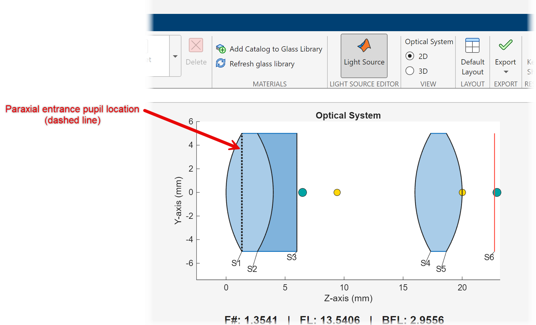
paraxialInfofunction, including the position, radius, and orientation of the paraxial entrance pupil.Display the paraxial entrance pupil on a 2-D visualization of the optical system by using the
view2dfunction and specifying theParaxialInfoname-value argument as"on". To get started with 2-D visualizations, see Visualize Optical Systems.Display the paraxial entrance pupil in the Optical System Designer app, indicated by a dashed line on the 2-D optical system visualization. This image shows a sample visualization in the app.
To get started with optical system analysis in the Optical System Designer app, see Design Optical System Using Optical System Designer and Analyze Optical System Using Optical System Designer.
Select Sampling Surface
The sampling surface is the surface at which the optical system
defines the initial ray positions and angles. To select the method by which the traceRays
function selects the sampling surface for traced rays, use the SamplingSurface
This table shows the type of sampling surface you can select depending on your use case.
SamplingSurface
Value | Description | Example Visualization |
|---|---|---|
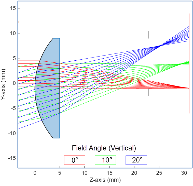
Entrance pupil — Specify the | Traces only the rays that enter the optical system through the entrance pupil and reach the image plane or last surface of the optical system. You can use this option to:
| The
|
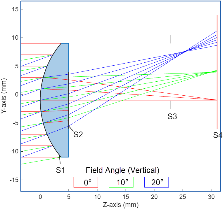
First surface — Specify | Traces rays at the first surface in the optical system. You can use this option to:
| The rays from three field points, defined by field angles, are sampled through the first surface of the optical system, S1.
|
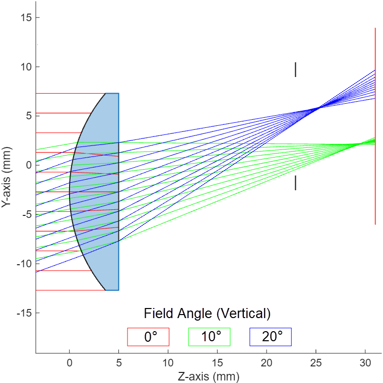
Entrance pupil, or first surface if the entrance pupil cannot be
found (default) — Specify
| If a ray passes through the entrance pupil and reaches the image
plane, You can use this option to:
| In this system, the lens is shifted vertically downwards. The rays from the first field point, in red, are sampled through the first surface, as they do not reach the image plane. The rays from the two field points at vertical angles 10 and 20 degrees, in green and blue respectively, are sampled through the actual entrance pupil of the optical system.
|
Note
traceRays supports only elliptical and rectangular entrance
pupils.
Note
When you use the Optical System Designer app to trace a set of rays through an optical system, the app automatically selects the sampling surface for each traced ray based on whether the ray reaches the image plane. If a traced rays does not reach the image plane, the app samples it at the first surface and visualizes as terminating at that surface.