转换器(低功率)
利用这些示例了解如何为低功率应用(低于 48 V)的转换器(例如 DC-DC 转换器、斩波转换器、降压转换器和升压转换器)进行建模。
精选示例
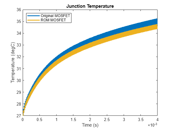
Improve Simulation Speed of Power Electronics Systems with Reduced Order Modeling
Enhance the model simulation speed of an electro-thermal DC-DC step-down converter by converting a high-fidelity switch to a reduced order model (ROM) switch. This conversion enables faster design iterations and analysis.
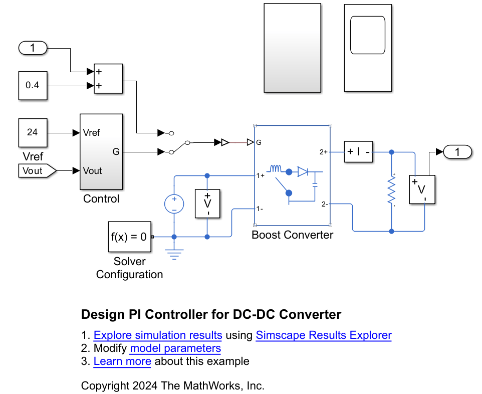
Design PI Controller for DC-DC Converter
Design a PI controller for a DC-DC converter using classical control theory. Alternatively, you can use Steady State Manager, Model Linearizer, Frequency Response Estimator, or PID tuner apps to streamline the design.
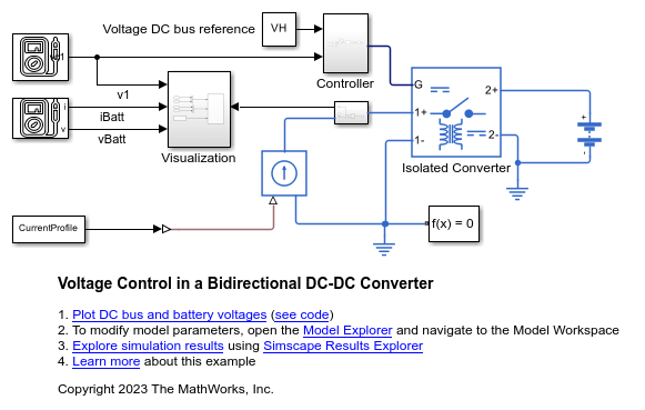
双向 DC-DC 转换器中的电压控制
此示例展示了如何使用隔离转换器控制连接到负载、电流源和电池的 DC 母线的电压。
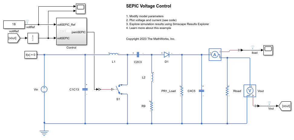
SEPIC 电压控制
此示例展示了如何控制单端初级电感转换器 (SEPIC) 的输出电压。SEPIC 是一种 DC-DC 转换器,旨在提供稳定的正输出电压,而无论输入电压是高于、等于还是低于预期输出电压。Control 子系统通过调整半导体开关的占空比来调节 SEPIC 的输出。为了调整占空比,Control 子系统使用基于 PI 的控制算法。在整个仿真过程中,输入电压保持恒定。通过电阻器为系统提供负载。总仿真时间为 0.1 秒。

Deploy SEPIC Model to FPGA
Deploy a single-ended primary-inductor converter (SEPIC) model to a Speedgoat® IO334-325K Simulink®-programmable I/O module and then run the model in real-time at a sample step size of 1 microsecond. The parts of the model that you deploy to CPU, run at 50 microseconds.
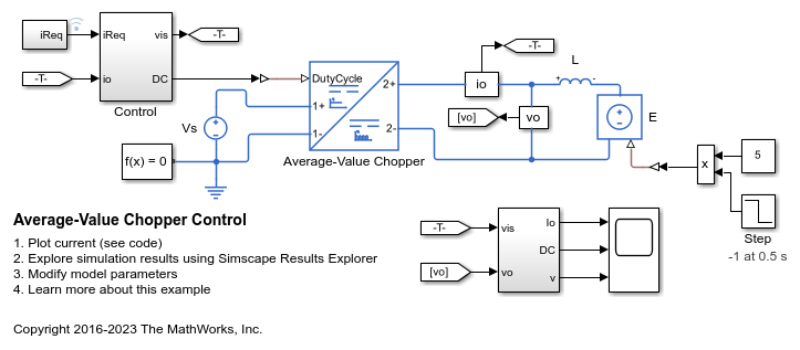
平均值斩波器控制
此示例展示了如何控制四象限斩波器。Control 子系统实现一种基于 PI 的简单控制算法来控制输出电流。平均值斩波器模型用于加快仿真速度。仿真同时使用正参考值和负参考值。总仿真时间 (t) 为 1 秒。在 t = 0.5 秒时,负载 DC 电源 E 的极性发生变化。
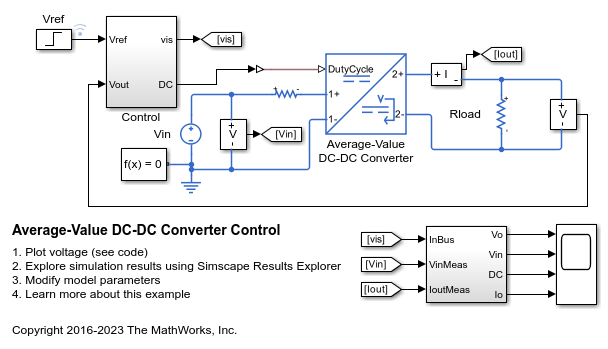
平均值 DC-DC 转换器控制
此示例展示了如何控制降压-升压转换器的输出电压。为了调整占空比,Control 子系统使用基于 PI 的控制算法。平均值 DC-DC 转换器模型用于加快仿真速度。在整个仿真过程中,输入电压和系统负载保持恒定。总仿真时间 (t) 为 0.25 秒。在 t = 0.15 秒时,参考电压发生变化,系统从降压模式切换为升压模式。
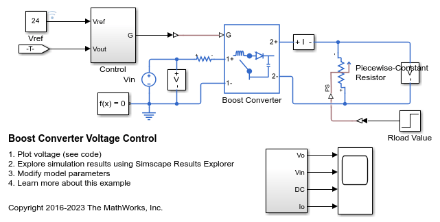
升压转换器电压控制
此示例展示了如何控制升压转换器的输出电压。为了调整占空比,Control 子系统使用基于 PI 的控制算法。在整个仿真过程中,输入电压被视为恒定的。一个可变电阻器为系统提供负载。总仿真时间 (t) 为 0.25 秒。在 t = 0.15 秒时,负载发生变化。
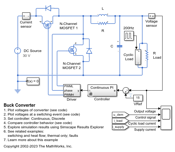
降压转换器
此示例展示了如何对将 30V DC 电源转换为 15V DC 稳压电源的开关电源进行建模。使用此模型确定电感 L 和平滑电容器 C 的大小,并设计反馈控制器。在连续控制器和离散控制器之间进行选择,以探索离散化的影响。
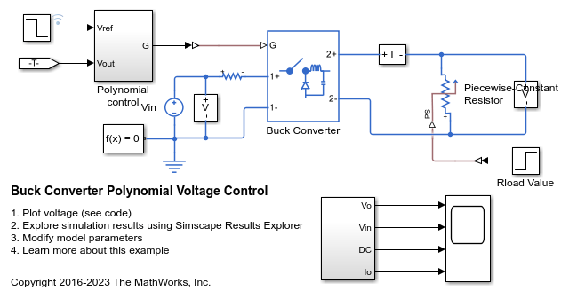
降压转换器多项式电压控制
此示例展示了如何使用多项式 RST 控制器来控制降压转换器的输出电压。RST 控制器调整占空比。在整个仿真过程中,输入电压被视为恒定的。一个可变电阻器为系统提供负载。总仿真时间 (t) 为 0.25 秒。在 t = 0.15 秒时,负载发生变化。在 t = 0.2 秒时,参考电压从 6 V 变为 4 V。
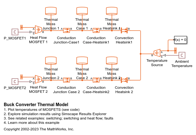
Buck Converter Thermal Model
Models the thermal dynamics of MOSFETs in a synchronous buck converter. It matches the structure of the 具有热动态特性的降压转换器 model. Omitting the electrical switching dynamics allows the simulation to take much larger time steps, dramatically reducing the amount of time it takes for the simulation to calculate steady-state temperatures for the MOSFETS.
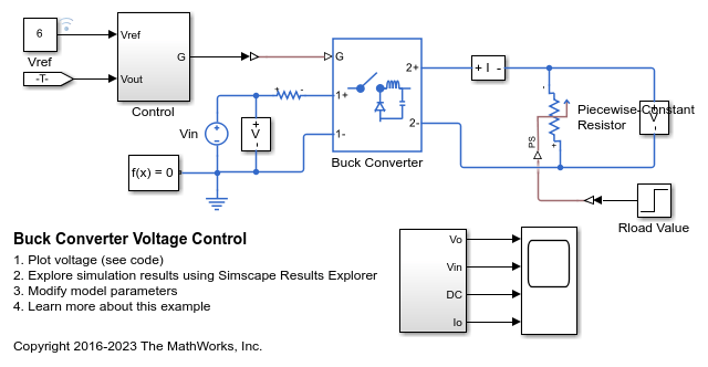
降压转换器电压控制
此示例展示了如何控制降压转换器的输出电压。为了调整占空比,Control 子系统使用基于 PI 的控制算法。在整个仿真过程中,输入电压被视为恒定的。一个可变电阻器为系统提供负载。总仿真时间 (t) 为 0.25 秒。在 t = 0.15 秒时,负载发生变化。
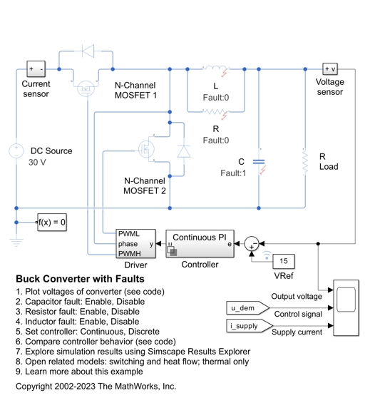
带故障系统的降压转换器
此示例展示了如何对开关电源运行中组件容差和故障事件产生的影响进行建模和评估。模型中已为 R、L 和 C 组件定义了容差、工作范围和故障。可在模块对话框中或通过 MATLAB® 命令启用故障。电容故障已预先启用,将在 1.5e-3 秒时触发。
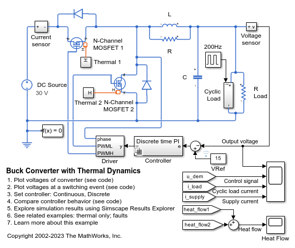
具有热动态特性的降压转换器
此示例展示了如何对将 30V DC 电源转换为 15V DC 稳压电源的开关电源进行建模。该模型既可用于确定电感 L 和平滑电容器 C 的大小,也可用于设计反馈控制器。通过在连续控制器和离散控制器之间进行选择,可以探索离散化的影响。将开关器件建模为 MOSFET 而非理想开关,可确保准确体现器件的导通电阻。此模型还能捕获器件的导通/关断时序,此时序主要取决于栅极电容值和 PWM 驱动器输出电阻。
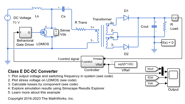
Class E DC-DC Converter
A Class E power converter with frequency control. A simple integral control is implemented in Simulink® in the Controller block, and is designed to deliver 100W into a 5ohm load. The switch is an LDMOS, high-voltage transistor with a nonlinear capacitance model, and R Trans is the equivalent series resistance of the transformer. The Output scope shows the drain-source voltage for evaluation of the voltage stress on the switch. Note that, due to the nonlinear output capacitance of the transistor, the peak voltage stress is higher than would be expected if the output capacitance were constant. In addition, the scope also shows the frequency control signal, the output voltage, and the reference value for the output voltage. This model can be used to calculate the output power information from components in the circuit.
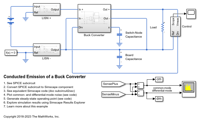
Conducted Emission of a Buck Converter
A buck converter configured for a measurement of common- and differential-mode noise on the source. In order to simulate the common-mode noise, the capacitive coupling between the circuit and a reference plane must be included in the model. In this circuit, the capacitance between the switching node (between the high- and low-side transistors) and the reference plane is also included.

DC-DC LLC 转换器
此示例展示了具有频率控制的 DC-DC LLC 功率转换器。Controller 模块在 Simulink® 中实现简单的积分控制。该积分控制实现变量 Vout_nominal 中指定的标称输出电压。Output 示波器显示频率控制信号、输出电压和输出电压参考值。在启动过程中,参考值逐渐增大至其所需的设定点。LLC 动力总成的设计是使用一次谐波逼近自动计算的。

First and Fourth Quadrant Chopper Control
Control a two-quadrant chopper. The two-quadrant chopper operates in the first and fourth quadrants, allowing positive and negative output voltage. The Control subsystem implements a simple PI-based control algorithm for controlling the output current. The total simulation time (t) is 0.5 seconds. At t = 0.25 seconds, the polarity of the load DC source E is changed.
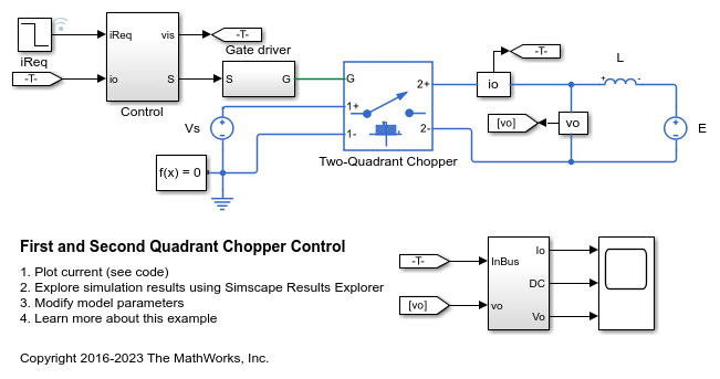
First and Second Quadrant Chopper Control
Control a two-quadrant chopper. The two-quadrant chopper operates in the first and second quadrants, allowing positive and negative output current. The Control subsystem implements a simple PI-based control algorithm for controlling the output current. The load of the system is considered constant throughout the simulation.
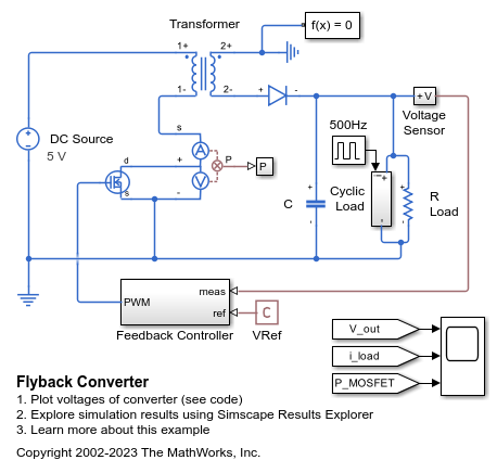
反激式转换器
此模型展示了反激式转换器如何将 5 V DC 电源升压为 15 V DC 稳压电源。通过在变压器一次侧产生时变电压来实现升压。变压器将电压升压,然后由二极管整流恢复为 DC。通过控制一次侧的开关频率来实现对输出电压的闭环控制。
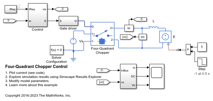
四象限斩波器控制
此示例展示了如何控制四象限斩波器。Control 子系统实现一种基于 PI 的简单控制算法来控制输出电流。仿真同时使用正参考值和负参考值。总仿真时间 (t) 为 1 秒。在 t = 0.5 秒时,负载 DC 电源 E 的极性发生变化。
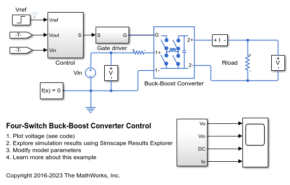
四开关降压-升压转换器控制
此示例展示了如何控制四开关降压-升压转换器的输出电压。为了调整占空比,Control 子系统使用基于 PI 的控制算法。在升压和降压模式下,均有一个开关控制占空比,一个开关反向工作,另外两个开关保持在固定位置。在整个仿真过程中,输入电压和系统负载被视为保持恒定。总仿真时间 (t) 为 0.25 秒。在 t = 0.15 秒时,参考电压发生变化,系统从降压模式切换为升压模式。
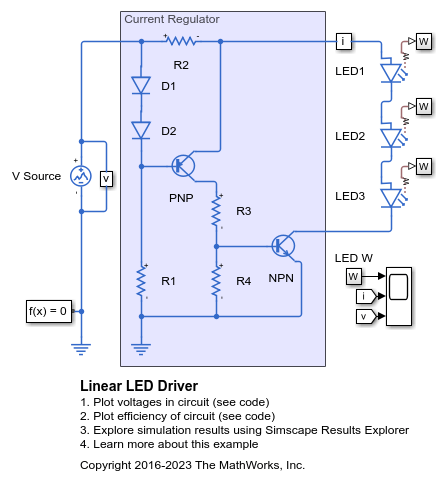
线性 LED 驱动
此示例展示了一个基于线性电流调节器的 LED 驱动。示波器显示光输出、电流输出和电源电压。当电源电压大于约 12 V 时,输出进入调节状态。

Linearize DC-DC Converter Model
Linearize a model of a DC-DC converter using averaged switching or an average-value converter.
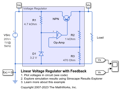
反馈型线性电压调节器
此示例展示了由离散组件构造的简单电压调节器电路。波动电源建模为 20 V DC 电压加上 1 V 正弦变化。齐纳二极管 D1 将运算放大器的非反相输入设置为 3.2 V,因此,由于运算放大器的增益较大,其反相输入和输出也为 3.2 V。因此,调节器电压输出调节为 3.2*(1000+470)/470 = 10 V。使用 NPN 双极晶体管可以提供比典型运算放大器所能提供的电流更高的电流。该模型可用于检查电路运行,并支持选择组件以实现所需的电压调节。
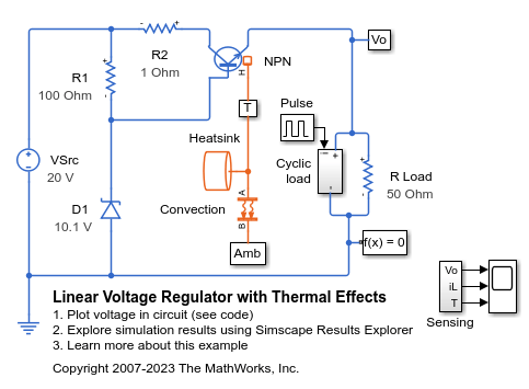
Linear Voltage Regulator with Thermal Effects
A low-cost voltage regulator circuit whose performance depends on both load current and temperature. Bias resistor R1 ensures that the voltage at the transistor base is close to the rated zener voltage. The regulator output voltage is also approximately at this voltage, the base-emitter voltage being a few tenths of a volt. The precise base-emitter voltage depends on the transistor working point (which in turn depends on the load) and also the temperature. Resistor R2 only serves to provide some protection in the event of a transient output short circuit.
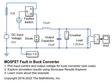
降压转换器中的 MOSFET 故障
此模型展示了如何将故障应用于功率转换器中的 MOSFET,以探索保护电路的运行情况。MOSFET 发生故障后,撬棒电路被激活,以钳制负载两端的输出电压,并最终导致保险丝熔断。

单象限斩波器控制
此示例展示了如何控制单象限斩波器。Control 子系统实现一种基于 PI 的简单控制算法来控制输出电流。
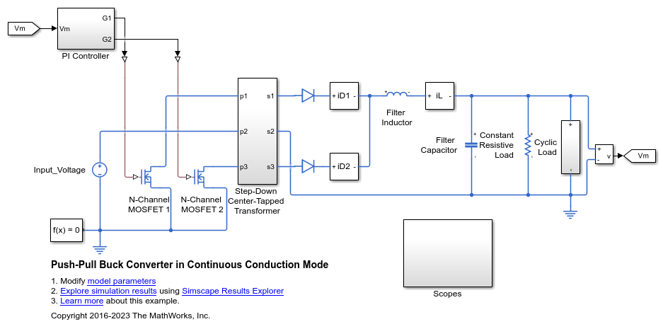
Push-Pull Buck Converter in Continuous Conduction Mode
Control the output voltage of a push-pull buck converter. The current flowing through the inductor is never zero. The DC-DC converter therefore operates in continuous conduction mode (CCM). To convert and maintain the nominal output voltage, the PI Controller subsystem uses a simple integral control. During startup, the reference voltage ramps up to the desired output voltage.
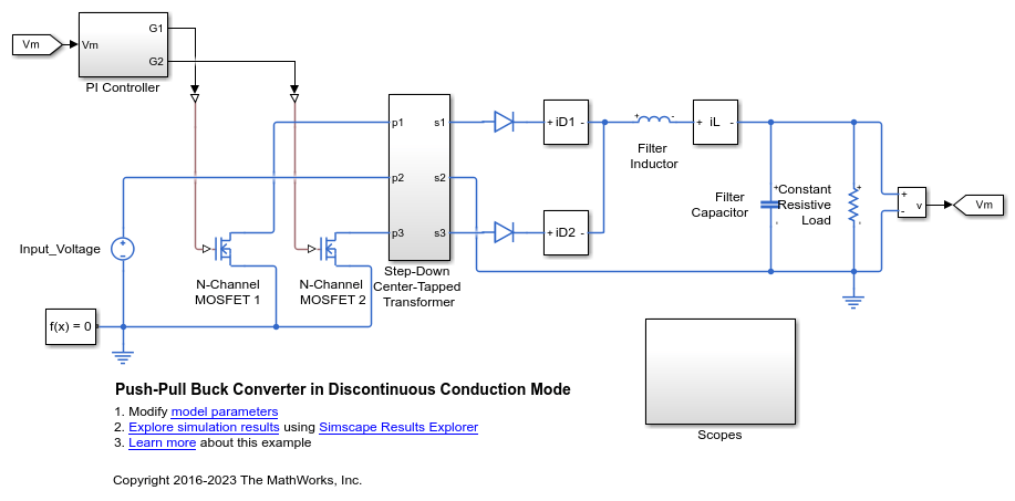
Push-Pull Buck Converter in Discontinuous Conduction Mode
Control the output voltage of a push-pull buck converter. The current flowing through the inductor reaches zero during the switch off cycle of the MOSFETs and therefore the DC-DC converter operates in Discontinuous Conduction Mode (DCM). This mode of conduction is mostly used for low-power applications. To convert and maintain the input DC voltage as a nominal output voltage, the PI Controller subsystem uses a simple integral control. During startup, the reference voltage is ramped up to the desired output voltage.
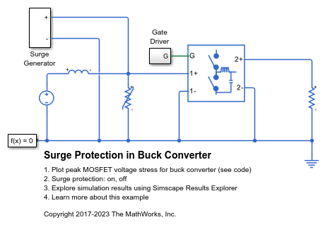
降压转换器中的浪涌保护
该模型展示了如何将压敏电阻应用于降压转换器,以保护开关 MOSFET 免受差模浪涌引起的过电压影响。
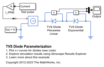
TVS Diode Parameterization
How to parameterize the Simscape™ Electrical™ diode to represent a Transient Voltage Suppression (TVS) diode. This example is for a TVS diode suited to protecting automotive electronics from voltage transients associated with turning off inductive loads. To view the data extracted from the datasheet, on the Modeling tab, in the Setup section, click Model Settings > Model Properties. On the Callbacks tab, click PreLoadFcn.
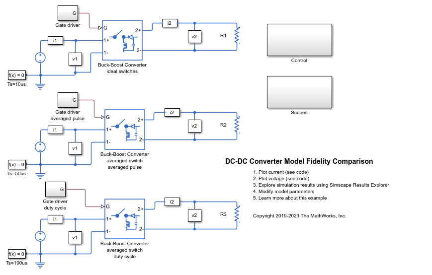
DC-DC Converter Model Fidelity Comparison
Use different levels of fidelity in DC-DC converters. The system contains three buck-boost converters. The top converter uses an ideal switch at a sample time of 10 us. To yield accurate results even though the model is under sampled at a sample time of 50 us, the middle converter uses an averaged switch with averaged pulse. To further increase the sample rate and to operate as an ideal averaged converter, the bottom converter uses an averaged switch and duty cycle instead of gate pulse. The Control subsystem contains a PWM generator. The Scopes subsystem contains Scope blocks that allow you to see the simulation results.

Compare Fidelity Levels of Chopper Converters
Use different levels of fidelity in chopper converters. You change the level of fidelity by changing the values for the Fidelity level, Switching device, and Integral protection diode parameters of the Four-Quadrant Chopper block. You also change the inputs to the G port. Using a higher level of fidelity improves the accuracy of the results but it also slows down simulation.
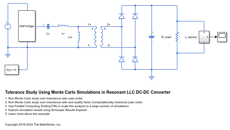
Tolerance Study Using Monte Carlo Simulations in Resonant LLC DC-DC Converter
Use Simscape™ Electrical™ to perform a Monte Carlo analysis to optimize the design of an LLC resonant DC-DC converter when some of its components have tolerances.
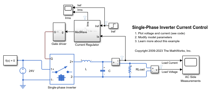
单相逆变器电流控制
此示例展示了如何控制单相逆变器系统中的电流。该单相逆变器采用由调制波形供电的平均开关。此示例适用于在专用实时仿真器上进行实时评估。
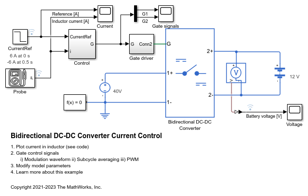
双向 DC-DC 转换器电流控制
此示例展示了如何控制双向 DC-DC 转换器的电感器电流。为了调整占空比,Control 子系统使用基于 PI 的控制算法。双向 DC-DC 转换器使用平均开关。为了实现不同的保真度级别,您可以使用调制波形、平均栅极脉冲或栅极脉冲。

两相 DC-DC 转换器电流控制
此示例展示了如何控制两相交错式双向 DC-DC 转换器的电流。该两相转换器包含两个带有理想 IGBT 的双向 DC-DC 转换器。为了调整占空比,Control 子系统使用基于 PI 的控制算法。为了减小转换器输出端口的波纹,两个相以相同的占空比切换,但存在 180 度的相对相移。Scopes 子系统包含示波器,可用于查看仿真结果。
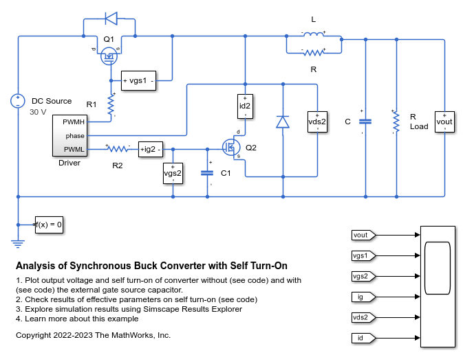
Analysis of Synchronous Buck Converter with Self Turn-On
How the MOSFET parameters affect the self turn-on mechanism and how you can prevent it.
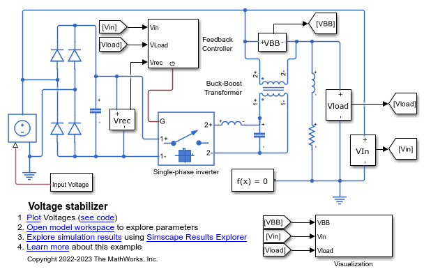
Power Converter Voltage Stabilizer
A voltage stabilizer circuit. It uses a full-wave rectifier, a single-wave inverter, and a buck-boost transformer to achieve voltage regulation.