Resolve Timing Failures in IP Core Generation and Simulink Real-Time FPGA I/O Workflows
Synchronous circuits require that data propagates from a source register to a destination register within one clock cycle. For the synthesis tools, the Delay blocks that you add to your Simulink® model run at the clock rate. The tools require data to travel between the blocks within one clock cycle. If the tool is unable to propagate the data between the registers for one or more signal paths in your model within one clock cycle, a timing failure occurs.
The tools report a slack information for each signal path, which corresponds to the difference between the required time and the arrival time. Required time is the expected time at which a signal must arrive at the destination register. Arrival time is the time elapsed for a signal to arrive at that point. A positive slack indicates that the signal arrived much faster than the required time, and the path passes the timing requirement. A negative slack indicates that the signal path is slower than the required time, and the path fails the timing requirement. To make sure that your design meets the timing requirements, speed up all signal paths that have a negative slack.
To identify if your design meets the timing requirements and how you can resolve timing failures, perform these steps.
Step 1: Identify the Timing Failure
When you run the IP Core Generation workflow or the
Simulink Real-Time FPGA I/O workflow for Vivado®-based boards, if your Simulink model does not meet the timing requirements, HDL Coder™ generates an error in the Build FPGA Bitstream
step of the workflow. See:
Get Started with IP Core Generation from Simulink Model for information about how to run the
IP Core Generationworkflow.FPGA Programming and Configuration on Speedgoat Simulink-Programmable I/O Modules for information about how to run the
Simulink Real-Time FPGA I/Oworkflow. When you run this workflow, use a Speedgoat board that supports Xilinx® Vivado as the synthesis tool.
When you run the Build FPGA Bitstream task, if you left the Run build process externally check box selected by default, whether or not there is a timing failure, HDL Coder displays the results as Passed and provides warning messages. View the build log in the external console to identify if there is a potential timing failure.
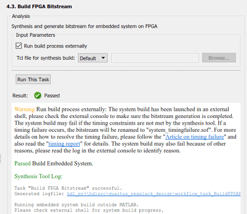
In the external console, if there is a timing
failure, you see the worst slack and this message: Timing constraints NOT
met!
When you clear the Run build process externally check box, and then run the Build FPGA Bitstream task, if a timing failure occurs, the task fails, and you see these messages in the Result subpane.
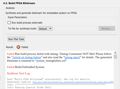
In both cases, when there is a timing failure, the code generator replaces the
previous bitstream with a bitstream that has the same name and the postfix
_timingfailure.bit or _timingfailure.sof
depending on whether you created a project by using Vivado or Quartus®. For example,
if the previous generated bitstream was called
system_top_wrapper.bit, and if there is a timing failure,
HDL Coder renames this bitstream to
system_top_wrapper_timingfailure.bit.
If you run the Program Target Device task, the task fails.
Report Timing Failures as Warnings
If you have already implemented the custom logic to resolve the timing failures, you can specify the timing failures to be reported as warnings instead of errors. You can then continue the workflow and generate the FPGA bitstream. Before programming the target SoC device, it is recommended that you have resolved the timing failures.
After you have resolved the timing failures, to verify that the failures have
been resolved, you can use the HDL Coder software. Change the timing failures to be reported as errors and
then rerun the IP Core Generation workflow to
ensure that the Build FPGA
Bitstream task passes. If the Build FPGA
Bitstream task still fails, perform the steps in the preceding
sections to identify and resolve the timing failures.
To specify timing failures to be reported as warnings:
After you run the Build FPGA Bitstream task, export the HDL Workflow Advisor to a script. In the script, to report timing failures as warnings, use the
ReportTimingFailureproperty of thehdlcoder.WorkflowConfigclass. You can then run the script or import the script to the HDL Workflow Advisor and then run the workflow.hWC.ReportTimingFailure = hdlcoder.ReportTiming.Warning;
If you are targeting a custom reference design that you have already defined for the board, to report timing failures as warnings, use the
ReportTimingFailureproperty of thehdlcoder.ReferenceDesignclass.hRD.ReportTimingFailure = hdlcoder.ReportTiming.Warning;
To learn how you can identify the critical path and resolve the timing failures, perform the steps in the preceding sections.
Step 2: Find the Critical Path
Critical path is a combinational path between the input and the output that has the maximum delay. This path corresponds to the signal path that has the worst negative slack. By identifying and optimizing the critical path, you can resolve timing failures and improve the timing of your design. You can identify the critical path in your design by using either of these strategies.
Strategy 1: Check the Timing Report
In the Result subpane, to open the timing report that is
generated by the synthesis tool, select the timing_report
link. You can use the report to identify the critical path in your design. In
the report, if you search for Worst Slack, you can identify
the worst setup slack. Then, use the Source and
Destination points to identify the critical path. For
example, this report for the LED blinking model
hdlcoder_led_blinking shows that the critical path is
inside the HDL Counter block.
-----------------------------------------------------------------------------------------
From Clock:  clk_out1_system_top_clk_wiz_0_0
  To Clock:  clk_out1_system_top_clk_wiz_0_0

Setup :   1193  Failing Endpoints,  Worst Slack   -2.478ns,  Total Violation  -1226.784ns
Hold  :      0  Failing Endpoints,  Worst Slack    0.034ns,  Total Violation      0.000ns
PW    :      2  Failing Endpoints,  Worst Slack   -0.576ns,  Total Violation     -0.731ns
-----------------------------------------------------------------------------------------

Max Delay Paths
-----------------------------------------------------------------------------------------
Slack (VIOLATED) : -2.478ns  (required time - arrival time)
  Source:     system_top_i/led_count_ip_0/U0/u_led_count_ip_dut_inst/
                   u_led_count_ip_src_led_counter/HDL_Counter1_out1_reg[0]/C
              (rising edge-triggered cell FDRE clocked by clk_out1_system_top_clk_wiz_0_0
                                               {rise@0.000ns fall@1.000ns period=2.000ns})
 Destination:  system_top_i/led_count_ip_0/U0/u_led_count_ip_dut_inst/
                    u_led_count_ip_src_led_counter/HDL_Counter1_out1_reg[20]/R
               (rising edge-triggered cell FDRE clocked by clk_out1_system_top_clk_wiz_0_0
                                                {rise@0.000ns fall@1.000ns period=2.000ns})
  Path Group:       clk_out1_system_top_clk_wiz_0_0
  Path Type:        Setup (Max at Slow Process Corner)
  Requirement:      2.000ns  (clk_out1_system_top_clk_wiz_0_0 rise@2.000ns -
                                            clk_out1_system_top_clk_wiz_0_0 rise@0.000ns)
  Data Path Delay:  3.899ns  (logic 1.412ns (36.211%)  route 2.487ns (63.789%))
Strategy 2: Estimate Critical Path Without Running Synthesis
Use HDL Coder to estimate and highlight the critical path in your model without synthesizing your design. Critical path estimation identifies the critical path by performing static timing analysis with timing data from target-specific databases. Estimating the critical path without using synthesis tools can lead to inaccurate timing results. Critical path estimation speeds up the process of identifying and optimizing the critical path in your design. It is an alternative to performing FPGA Synthesis and Analysis with the HDL Workflow Advisor. To learn more, see Critical Path Estimation Without Running Synthesis.
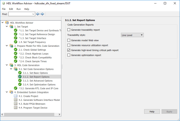
To estimate the critical path, in the Set Report Options task, select the Generate high-level timing critical path report check box. Run the workflow to the Generate RTL Code and IP Core task.
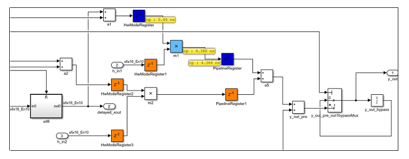
HDL Coder generates a critical path estimation section in the Code
Generation Report. On this section, when you select the link to the
criticalpathestimated script, the code generator
highlights the critical path in the generated model. This figure shows a section
of the hdlcoder_sfir_fixed_stream model with the critical
path highlighted.
Strategy 3: Annotate Critical Path By Using Backannotation
For more accurate critical path information and
highlighting of critical path in your design, use backannotation. To use
backannotation, you have to leave the current Workflow Advisor session, and then
run the Generic ASIC/FPGA workflow to annotate the model with
the synthesis results.
Before you use backannotation, it is recommended that you export the current HDL Workflow Advisor settings to a script. By exporting the settings to a script, you can iterate on the critical path and customize various settings to optimize your design until you meet the timing requirements. You can import the Workflow Advisor script to the HDL Workflow Advisor and then run the workflow. See also Run HDL Workflow with a Script.
To use backannotation:
In the Set Target Device and Synthesis Tool task, select
Generic ASIC/FPGAas the Target workflow. For Synthesis tool, specify the same tool that you used to run theIP Core Generationworkflow.When you specify these settings, HDL Coder resets this task and all tasks that follow it.
Select Run This Task.
In the Set Target Frequency task, specify the same target frequency that you used to run the
IP Core
                                    Generation
workflow. Select Run This Task.Right-click the Annotate Model with Synthesis Result task and select Run to Selected Task.
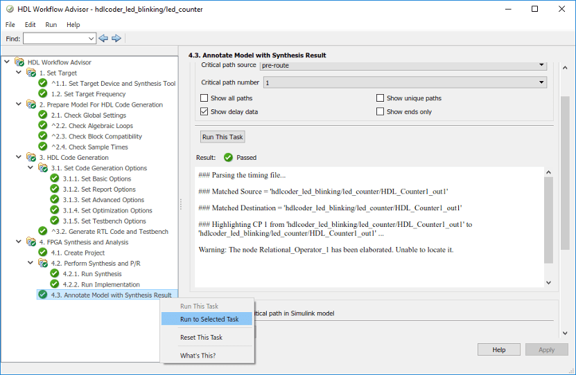
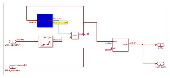
When you run the link to the Annotate Model with Synthesis
Result task, the code generator highlights the critical path in
the generated model. This figure shows that the critical path in the
hdlcoder_led_blinking model is inside the HDL
Counter block.
Step 3: Resolve Timing Failures
To resolve timing failures, you can use any of these recommendations or a combination of the recommendations until your design meets the target frequency.
Recommendation 1: Use Speed Optimizations
You can use speed optimizations such as distributed pipelining and clock-rate pipelining to break the critical path by adding pipeline registers while preserving the functional behavior. By reducing the critical path, you can achieve higher clock frequencies and increase the arrival time of the signal until it equals the required time and the slack becomes zero.
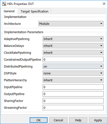
Distributed pipelining optimization move the existing delays you have in your
design across the subsystem hierarchy. To enable distributed pipelining on a
subsystem, set DistributedPipelining as
on. If your design does not meet the timing
requirements, you can add more pipelines by using
InputPipeline or OutputPipeline
block properties. You can specify these properties in the HDL Block Properties
dialog box of the Subsystem.
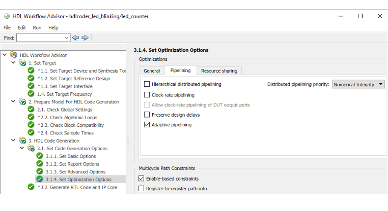
If distributed pipelining is unable to move the registers, you can add Delay blocks to your model, and then disable the Allow design delay distribution setting. Reset the Check Global Settings task and run the workflow to the Build FPGA Bitstream task. You can iterate on this approach and use other optimizations such as clock-rate pipelining with a large value for the Oversampling factor if the design does not meet the timing requirements. To specify these settings, use the Pipelining tab of the Set Optimization Options task in the HDL Workflow Advisor. For more information, see Speed Optimization.
Recommendation 2: Specify Enable-Based Multicycle Path Constraints
If your design contains multiple sample rates or uses certain HDL block implementations or speed optimizations that insert pipeline registers at a faster rate after code generation, your design can have multicycle paths. By default, HDL Coder uses a single clock mode that generates a primary clock at the fastest sample rate and creates a timing controller entity. The timing controller generates a set of clock enables with the required rate and phase information to sample the clock signal for blocks that operate at a slower sample time.
If your critical path is on a slower signal rate, synthesis tools can fail to meet the timing requirements. A timing failure occurs because the tools cannot infer the sample rates from the generated HDL code and assume that these paths have to run at the fastest rate. You can use enable-based multicycle path constraints to generate a constraints file that enables the synthesis tool to ease the clock constraint on the multicycle paths. To specify generation of multicycle path constraints, in the Set Optimization Options task, select the Enable-based constraints check box. Run the workflow to the Build FPGA Bitstream task. For an example, see Use Multicycle Path Constraints to Meet Timing for Slow Paths.
Recommendation 3: Reduce the Target Frequency
Use the Target Frequency (MHz) setting to specify the target frequency for HDL Coder to modify the clock module setting in the reference design to produce the clock signal with that frequency. See also Target Frequency.
To resolve timing failures, reduce the Target Frequency
(MHz) setting so that the synthesis tool can meet the timing
constraint. To see what target frequency you can specify, use the slack and the
critical path information from the synthesis tool timing report. Because slack
is equal to the difference between the required time and arrival time, you can
add the slack to the required time, and then use this sum as the New
required time. Use the reciprocal of this New required
time as the target frequency value to meet the timing requirements
because the New required time equals the arrival time. To
compute the target frequency, in the MATLAB® Command Window, run this script.
% Specify the required time (ns) and slack (ns) using timing report
required_time = 2;
slack = 2.2;

% Slack is difference between required_time and arrival_time
% By adding slack to required_time you can resolve
New_required_time = required_time + slack;
Target_frequency = 1 / (New_required_time);

% Since we computed the new time in nanoseconds
Target_frequency_MHz = Target_frequency * 10^3;
In the Set Target Frequency task, specify this value for Target Frequency (MHz), and then run the workflow to the Build FPGA Bitstream task. If you see a timing failure, you can use this approach to iterate on the target frequency value until your design meets the timing requirements and the slack becomes zero.
You can also export the HDL Workflow Advisor settings to a script and keep
iterating on the target frequency value by specifying
Target_frequency_MHz as the value for the
TargetFrequency property. Then, run the script.
% Set this frequency as the new target frequency
hdlset_param('hdlcoder_led_blinking', 'TargetFrequency', Target_frequency_MHz);
See Also
hdlcoder.Board | hdlcoder.ReferenceDesign