Generate SystemVerilog Assertions and Functional Coverage
SystemVerilog DPI component generation and Universal Verification Methodology (UVM)
testbench generation workflows enable you to reuse Simulink® verification models in the resulting SystemVerilog. Simulink model verification blocks such as Assertion (Simulink) or Check Dynamic Lower Bound (Simulink), and calls to
verify (Simulink Test)
statements create error checks and functional coverage points in the generated
SystemVerilog.
When a Simulink assertion or verify call fails, it generates a
SystemVerilog error by default. When either succeeds, it generates a SystemVerilog cover point which logs a PASS result. Assertions and
verify statement behaviors can be customized using SystemVerilog command line arguments and the HDL Verifier Assertion block. For more
information about customization, see Customize Assertion.
Create a Simulink Testbench Model
In Simulink, create a model for the device under test (DUT), and then create a
testbench for the model. You can use a combination of assertion blocks from the
Simulink / Model Verification library and blocks that contain
verify statements from the Simulink Test library, such
as:
A
verify(Simulink Test) statementA block from the Model Verification (Simulink) library
An HDL Verifier™ Assertion block
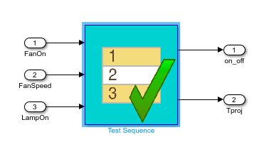
Create Simulink Test Sequence
In your testbench model, include a verify statement by
adding one or more of these blocks:
Test Assessment (Simulink Test)
Test Sequence (Simulink Test)
Chart (Stateflow)
To create and edit test steps, use the Test Sequence Editor (Simulink Test). In the
test sequence, use verify statements to assess the
simulation, as described in Define Test Steps and Assessments (Simulink Test).
The verify statement and the Test Sequence
block represent a temporal check in Simulink. When you generate a SystemVerilog DPI component, the temporal logic is located in the generated C
code. The SystemVerilog wrapper contains an immediate assertion that triggers when the
verify condition is violated.
Include Simulink Model Verification Blocks
You can also include these assertion blocks from the Simulink / Model Verification (Simulink) library.
Assertion (Simulink)
Check Dynamic Gap (Simulink)
Check Dynamic Range (Simulink)
Check Static Gap (Simulink)
Check Static Range (Simulink)
Check Dynamic Lower Bound (Simulink)
Check Dynamic Upper Bound (Simulink)
Check Input Resolution (Simulink)
Check Static Lower Bound (Simulink)
Check Static Upper Bound (Simulink)
Check Discrete Gradient (Simulink)
In addition, you can include the HDL Verifier Assertion block to create customizable assertions. For an example that uses the HDL Verifier Assertion block, see Generate Native SystemVerilog Assertions from Simulink.
In SystemVerilog, every model verification block and verify
statement is mapped to an assertion and a coverage point. You can adjust
coverage goals, filter specific assertions, and see verbose information for each
of the verify statements.
You can use multiple verify statements and assertion blocks
in your model.
When simulating your design in Simulink, the simulation warns if the assertion or the
verify assessment fails.
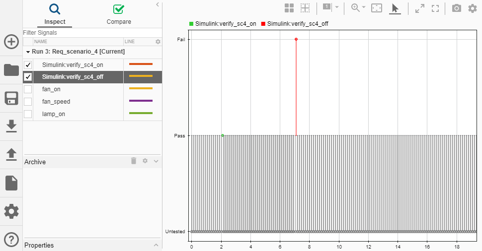
You can view and inspect the simulation results by using the Simulation Data Inspector (Simulink). Open the Simulation Data Inspector by entering this code at the MATLAB® command prompt.
Simulink.sdi.view
To view signals over time, select them in the left pane of the Simulation Data Inspector.
Customize Assertion
You can customize the SystemVerilog immediate assertion in two ways:
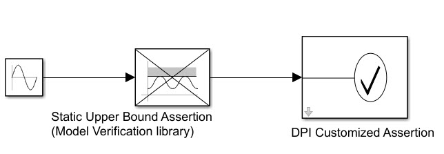
Include an HDL Verifier Assertion block, and customize the generated SystemVerilog immediate assertion. You can set a custom message when the assertion fails and can choose between warning, error, or a custom command when the assertion fails. For an example that uses the HDL Verifier Assertion block, see Generate Native SystemVerilog Assertions from Simulink. The result is similar to this figure.
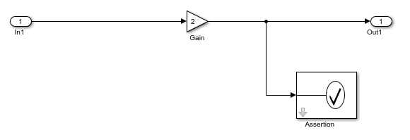
To customize an assertion from the Model Verification library, connect the block output to a customizable HDL Verifier Assertion block, by following these steps.
Add a block from the Simulink / Model Verification library to your model.
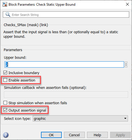
Open the block mask, and then set these parameters (as shown in this figure):
Clear the Enable assertion parameter to prevent redundant assertion outputs.
Select the Output assertion signal parameter to create a boolean output signal that captures the assertion.
Add an Assertion block from the HDL Verifier / For Use with DPI-C SystemVerilog library, and connect the output signal of the Model Verification block to the input port of the Assertion block.
Customize the Assertion block by following the steps in the Generate Assertions Workflow example.
The result is similar to this figure.
Generate a UVM or SystemVerilog DPI Component
Configure the Model for Code Generation
In the Configuration Parameters dialog box, select Code
Generation in the left pane. Under Target
Selection, set System Target File to
systemverilog_dpi_grt.tlc or to
systemverilog_dpi_ert.tlc when using Embedded Coder®.
Select SystemVerilog DPI in the left pane. Under SystemVerilog Ports, set the data type and connection settings. Click OK.
Generate a UVM or SystemVerilog DPI Component
Note
To generate a UVM or DPI Component, the assertion or test block must be inside a Simulink subsystem.
Use the slbuild (Simulink) function to build the
system. For example, to build a subsystem named
My_verify_tst, enter this code at the MATLAB command
line.
slbuild('My_verify_tst');You can also use the uvmbuild function to generate a UVM testbench. If your test
model contains verify statements, they are mapped to
assertions in your UVM environment, and coverage data is collected.
Run HDL Simulation with the Generated Component
Change your current folder to the dpi_tb folder, which is under
the code generation folder in your HDL simulator installation. Start your HDL
simulator, and run the generated script to start the simulation. The simulation
output is consistent with the Simulink output.
After the simulation completes, coverage information is displayed for each assertion. By default, an assertion is considered covered if it was evaluated at least once.
For additional information on running the HDL simulation, see Verify Generated Component Against Simulink Data.
Filter Assertions and Coverage Reports
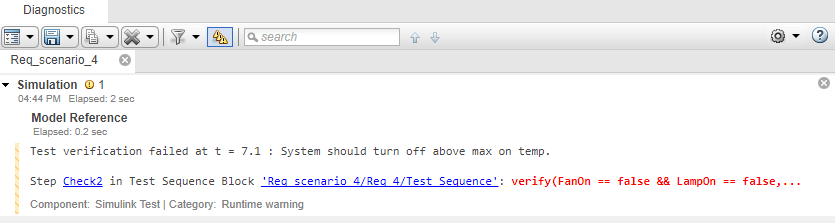
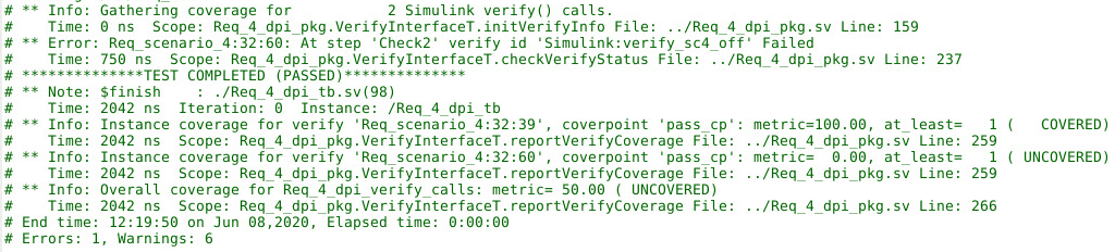
Each generated error or warning displays a unique name identifying its origin.
That number is the unique Simulink identifier (SID) of that block. For example, this log shows an error
that was generated by a block with SID
Req_scenario_4:32:60.
# ** Error: Req_scenario_4:32:60: At step 'Check2' verify id 'Simulink:verify_sc4_off' Failed
You might have several steps in a test sequence that utilize a
verify assessment or several DPI components logging warnings
from a simulation. In your test model, you can filter the generated output for
specific verify checks by specifying the associated SID as a plus
argument on the command line and equating the SID to -1. For
example, to turn off all of the output and functional coverage for SID
Req_scenario_4:32:60, enter this code at the HDL command
line.
vsim -c -sv_lib ../Req_4 work.Req_4_dpi_tb +Req_scenario_4:32:60=-1
Adjust Functional Coverage Goals
You can use assertion blocks and verify statements to gather
functional coverage during a SystemVerilog simulation. After generating SystemVerilog using the uvmbuild or slbuild (Simulink) functions, define coverage
goals for each assertion. After a SystemVerilog simulation completes, view the results in the generated log file, or
use a third party tool to extract the results. The default coverage goal is at least
one passing execution of the assertion or verify call.
To increase the functional coverage goal for a specific assertion, specify the
associated SID as a plus argument in the command line, and equate the SID to your
coverage goal. For example, to increase the coverage goal of a
verify statement with SID
Req_scenario_4:32:60 from the default of one to two passing
checks, enter this code at the HDL command line.
vsim -c -sv_lib ../Req_4 work.Req_4_dpi_tb +Req_scenario_4:32:60=2
Verbose Mode
By default, the generated DPI component outputs an error when a functional
coverage point is evaluated and fails. To see additional output generated by the
functional coverage point, enter the argument +VERBOSE_VERIFY at
the HDL simulation command line. This argument adds this additional information:
UNTESTED– When the functional coverage point was not evaluatedPASSED– When the functional coverage point was evaluated and the test passed
For example, when using ModelSim™, enter this code at the command line.
vsim -c -sv_lib ../Req_4 work.Req_4_dpi_tb +VERBOSE_VERIFY
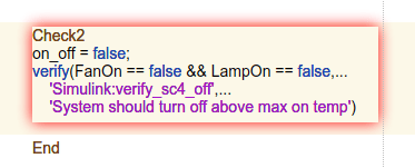
Trace Generated SystemVerilog Error Back to Simulink Source
After running a SystemVerilog simulation with a generated test sequence, your log file displays
warnings and errors. To identify which block originated a specific warning or error
output, use the hilite_system (Simulink) function.
For example, to highlight the block that generated a warning for SID
Req_scenario_4:32:60, enter this code at the MATLAB command line.
hilite_system('Req_scenario_4:32:60');This figure highlights the verify statement and the test sequence block that created the warning.
See Also
Blocks
- Test Sequence (Simulink Test) | Test Assessment (Simulink Test) | Chart (Stateflow) | Assertion (Simulink) | Check Dynamic Gap (Simulink) | Check Dynamic Range (Simulink) | Check Static Gap (Simulink) | Check Static Range (Simulink) | Check Dynamic Lower Bound (Simulink) | Check Dynamic Upper Bound (Simulink) | Check Input Resolution (Simulink) | Check Static Lower Bound (Simulink) | Check Static Upper Bound (Simulink) | Check Discrete Gradient (Simulink)
MATLAB Language Syntax
- verify (Simulink Test)