Build Mining Truck 3D Asset Using Primitive Shapes for Robotics Simulation
R2026bThis example shows how to construct a hierarchical 3D model of an offroad mining haul truck using primitive shapes such as cylinders, toruses, and boxes, and organize it within a scene graph.
In this example, you:
Define the truck configuration parameters such as dimensions, colors, and articulation pose.
Create primitive shapes representing one wheel using toruses, cylinders, and spheres.
Apply spatial transformations to orient and position each component in 3D space.
Assign physically-based materials to control the appearance of each part.
Merge the wheel parts into a single mesh and replicate it to each axle position.
Assemble the remaining subsystems such as chassis, dump bed, and hydraulic cylinders.
Organize the parts into six rigid bodies in a hierarchical scene graph.
Build a
rigidBodyTree(Robotics System Toolbox) model from the asset for off-road robotics simulation.Export the complete hierarchical scene to a GLB file.
The model supports rotation of each wheel about its axle and tilting of the dump bed about its tilt axis. A rigidBodyTree represents the truck as a set of rigid bodies connected by joints, where each body owns its visual mesh. In this example, you build the 3D asset around the six independently moving rigid bodies of the truck.
The truck is a rigid-frame, rear-dump mining vehicle with one steered front axle and one driven rear axle with dual tires on each side, typically used in open-pit mining operations. A rigid-frame truck has a single, non-hinged chassis and steers by turning its front wheels, unlike an articulated hauler that bends at a central pivot joint. Rear-dump means the bed tilts up at the front to unload material out the back.
The six rigid bodies are:
Chassis — Frame, engine, cab, hydraulic cylinders, stairs, and all other non-wheel, non-bed components
Bed — Dump body that pivots about the rear hinge during operation
WheelFR — Front right wheel
WheelFL — Front left wheel
WheelRR — Rear right dual wheels
WheelRL — Rear left dual wheels
Define Truck Configuration
Before constructing geometry, you need a centralized set of parameters that ensures all subsystems align correctly. For example, wheel radii must match axle positions, frame dimensions must accommodate the dump bed pivot, and colors must be consistent across the entire truck.
Define the configuration of the truck by using the helperMiningTruckConfig helper function. The helper function returns three structures:
dim— Truck dimensions and component positions, returned as a structure. Units are in meters.color— Color palette for all truck surfaces, returned as a structure. Each field is a 1-by-3 RGB triple in the range [0, 1].cfg— Articulation pose angles such as bed tilt and wheel steer, returned as a structure. Units are in degrees.
[dim,color,cfg] = helperMiningTruckConfig;
Build Wheel at Origin
In this example, you incrementally build the truck 3D asset by assembling its subsystems. You begin with one wheel built at the origin from a torus tire skeleton, two chevron rows of tread lugs, sidewall ridges and bead rings, a hub, a rim, five spokes, eight lug nuts, and a center cap. You then merge those parts into one rigid-body mesh, and copy-translate that mesh to each axle position. This is how every wheel on the truck is produced from a single authored geometry.
Start with the tire skeleton. The tire is a torus with a major radius equal to the tire center radius minus half the tire width, and a minor radius equal to half the tire width.
Display the radius and width of the tire module.
disp([dim.tireRadius dim.tireWidth]) % Tyre radius and width in meters1.5500 0.8500
Create the primitive shapes by using the helperCreatePrimitiveShape helper function. This function uses the primitive type, tire parameters, and number of major and minor loop sections to create a Mesh object representing the shape.
tire = helperCreatePrimitiveShape("torus",dim.tireMajor,dim.tireMinor, ...
    majorSections=48,minorSections=24);
Visualize the mesh by using the patch object function.
figure
patch(tire)
camlight
title("Tire (torus, unrotated)")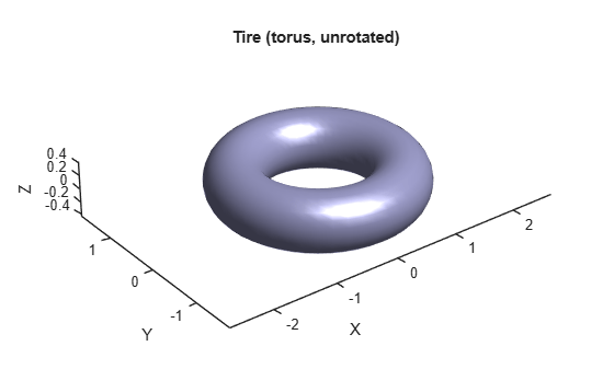
The generated mesh represents the torus in the XY-plane.
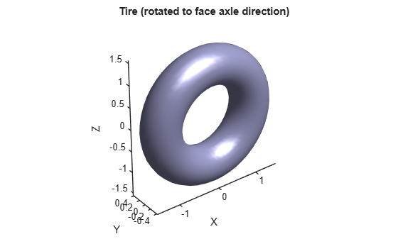
Rotate it 90 degrees about the X-axis to stand it up like a wheel facing along Y-axis by using the rotate object function and display the mesh.
rotate(tire,[deg2rad(90) 0 0])
figure
patch(tire)
camlight
axis tight
title("Tire (rotated to face axle direction)")
Display the defined color of the tire.
disp(color.tireBlack) % RGB, near-black rubber0.0800 0.0800 0.0800
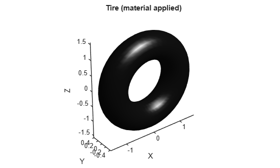
Assign a physically-based material to the tire. Create a material by using the Material object. A MetallicFactor of 0 indicates dielectric rubber and a RoughnessFactor of 0.5 results in the matte surface of an industrial tire.
tire.Material = asset3d.Material(BaseColorFactor=color.tireBlack,MetallicFactor=0,RoughnessFactor=0.5);
Display the tire mesh with applied material.
figure
patch(tire)
axis tight
camlight
title("Tire (material applied)")
Build Hub, Rim, and Center Cap
Build the hub as a short cylinder along the axle Z-axis by using the helperCreatePrimitiveShape helper function.
hub = helperCreatePrimitiveShape("cylinder",dim.hubRadius,dim.hubWidth,sections=32);Rotate the mesh 90 degrees about the X-axis to lay it along Y-axis, assign a physically-based material to the hub, and display the hub.
rotate(hub,[deg2rad(90) 0 0])
hub.Material = asset3d.Material(BaseColorFactor=color.hubDarkGray,MetallicFactor=0,RoughnessFactor=0.5);
figure
patch(hub)
camlight
title("Hub")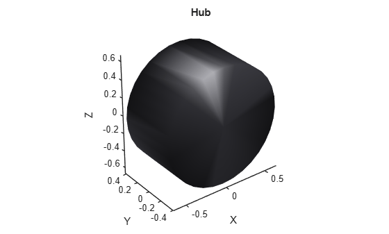
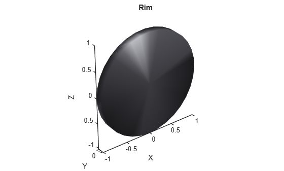
Build the rim with the same rotate pattern as the hub, but with a larger radius and thinner width such that it forms the disc with attached spokes.
Rotate and apply material to the rim, and display it.
rim = helperCreatePrimitiveShape("cylinder",dim.rimRadius,dim.rimWidth,sections=32);
rotate(rim,[deg2rad(90) 0 0])
rim.Material = asset3d.Material(BaseColorFactor=color.rimGray,MetallicFactor=0,RoughnessFactor=0.5);
figure
patch(rim)
camlight
axis tight
title("Rim")
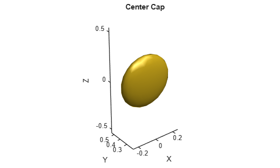
Build the center cap, which is a sphere flattened along the axle direction such that it renders as a domed bolt cover at the hub center.
Scale, translate, and apply material to the cap, and display it.
cap = helperCreatePrimitiveShape("sphere",dim.hubRadius*0.4,subdivisions=2);
scale(cap,[1 0.3 1])
translate(cap,[0 dim.hubWidth/2 + 0.02 0])
cap.Material = asset3d.Material(BaseColorFactor=color.catYellow,MetallicFactor=0,RoughnessFactor=0.5);
figure
patch(cap)
camlight
title("Center Cap")
Stage Wheel Parts in Scene
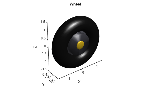
Organize the wheel parts into a hierarchy so they can be merged as one rigid body. Create a staging Scene object wheelStage and add the named parts by using the addMesh object function. The tire becomes the parent node and the hub, rim, and cap attach as its children. Create a copy of the cap and translate it to the inner face.
wheelStage = asset3d.Scene(BaseFrame="Wheel");
addMesh(wheelStage,tire,NodeName="Tire")
addMesh(wheelStage,hub,NodeName="Hub",ParentNodeName="Tire")
addMesh(wheelStage,rim,NodeName="Rim",ParentNodeName="Tire")
addMesh(wheelStage,cap,NodeName="Cap",ParentNodeName="Tire")
cap2 = copy(cap);
translate(cap2,[0 -dim.hubWidth - 0.04 0])
addMesh(wheelStage,cap2,NodeName="Cap Inner",ParentNodeName="Tire")
Visualize all parts of the wheel.
figure(Name="Wheel")
patch(wheelStage)
camlight
title("Wheel")
Add Tread, Sidewalls, Spokes, Lug Nuts and Merge Wheel
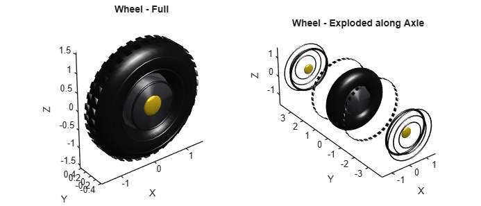
The remaining wheel parts are repetitive: two chevron rows of tread lugs around the tire, sidewall ridges and bead rings on each face, five spokes on the rim, and eight lug nuts on the hub. Attach them as children of the "Tire" node in wheelStage and merge the staged scene into a single Mesh by using the helperAddWheelDetailsAndMerge helper function. The helper function flattens wheelStage with Concatenate=true and returns one mesh that carries all wheel geometry and vertex colors.
wheelMesh = helperAddWheelDetailsAndMerge(wheelStage,dim,color);
Visualize the fully populated wheelStage together with its exploded view and observe tread lugs, sidewall ridges, spokes, and lug nuts.
figure(Name="Wheel - Full",Position=[100 100 1400 600])
subplot(1,2,1)
patch(wheelStage)
camlight
title("Wheel - Full")
subplot(1,2,2)
patch(wheelStage,Explode=true,ExplodeVector=[0 3 0])
camlight
title("Wheel - Exploded along Axle")
Place Wheels and Add to Scene
Place each wheel by copying the merged mesh and translating each copy to its axle position. For the dual rear pair on each side, the two tires (outer and inner) share a rigid-body parent node in the scene graph such that they always move together. The wheel positions and the rigid-body assignments are defined in dim.tirePositions and dim.tireGroup, respectively.
Create a new scene by using the Scene object. Add each tire copy by using the addMesh object function. The first tire of a rigid body represents the group node, and the second one (for the dual rears) attaches as its child.
truckScene = asset3d.Scene(BaseFrame="MiningTruck");
wheelGroups = unique(string(dim.tireGroup),"stable");
for gi = 1:numel(wheelGroups)
    g = wheelGroups(gi);
    idx = find(string(dim.tireGroup) == g);
    if isscalar(idx)
        % Single tire in this group -- copy and place directly.
        c = copy(wheelMesh);
        translate(c,dim.tirePositions(idx,:))
        addMesh(truckScene,c,NodeName=g)
    else
        % Dual rear: stage every tire in the group on a tiny scene and
        % flatten to one mesh so the rigid body has no children.
        stage = asset3d.Scene(BaseFrame=g);
        for k = 1:numel(idx)
            c = copy(wheelMesh);
            translate(c,dim.tirePositions(idx(k),:))
            if k == 1
                addMesh(stage,c,NodeName="Outer")
            else
                addMesh(stage,c,NodeName="Inner",ParentNodeName="Outer")
            end
        end
        addMesh(truckScene,flatten(stage,Concatenate=true),NodeName=g)
    end
end
Visualize Assembled Wheels
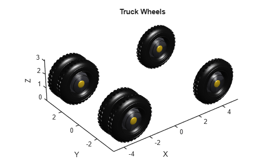
Before adding the rest of the truck, visualize, and verify that all four wheel rigid bodies are correctly placed and oriented.
figure(Name="Wheels")
patch(truckScene)
camlight
title("Truck Wheels")
Build Remaining Subsystems
Building the chassis, dump bed, and hydraulic cylinders one-by-one in the main script would be impractical. Assemble the remaining subsystems by using the helperBuildMiningTruckSubsystems helper function. The helper function builds the chassis frame and bodywork, dump bed, and hydraulic cylinders, and attaches each component to the scene. It returns the updated truckScene and truckMesh. The mesh truckMesh represents the full truck flattened into a single Mesh object for fast static previews. Use wheel groups as the existingGroups argument since they already exist in the scene.
existingGroups = wheelGroups;
[truckScene,truckMesh] = helperBuildMiningTruckSubsystems(truckScene,dim,color,cfg,existingGroups);
Inspect Scene Hierarchy
The scene contains six rigid bodies with many sub-parts. Verify that each part is attached to the intended parent node. Print the scene graph as a tree by using the dispGraph object function. Each top-level node is one of the six rigid bodies, and children represent individual sub-parts.
dispGraph(truckScene)
MiningTruck
    ├── WheelFR [Mesh: 8668 faces]
    ├── WheelFL [Mesh: 8668 faces]
    ├── WheelRR [Mesh: 17336 faces]
    ├── WheelRL [Mesh: 17336 faces]
    ├── Chassis [Mesh: 3704 faces]
    └── Bed [Mesh: 1560 faces]
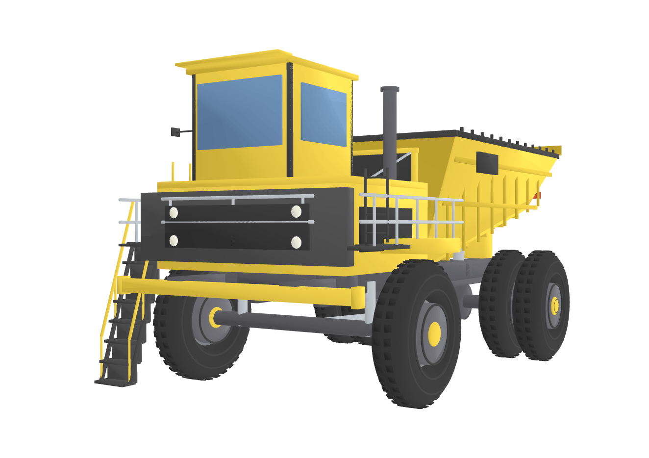
Visualize the assembled scene in an interactive 3D viewer by using the show object function.
show(truckScene)
Visualize Truck Scene
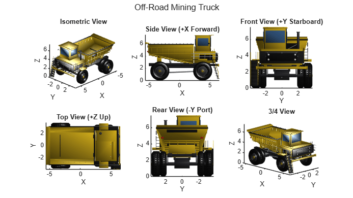
A single perspective can hide alignment errors or missing parts. Inspect the model from six standardized orthographic angles by using the helperShowMiningTruckOrthographicViews helper function.
helperShowMiningTruckOrthographicViews(truckMesh)
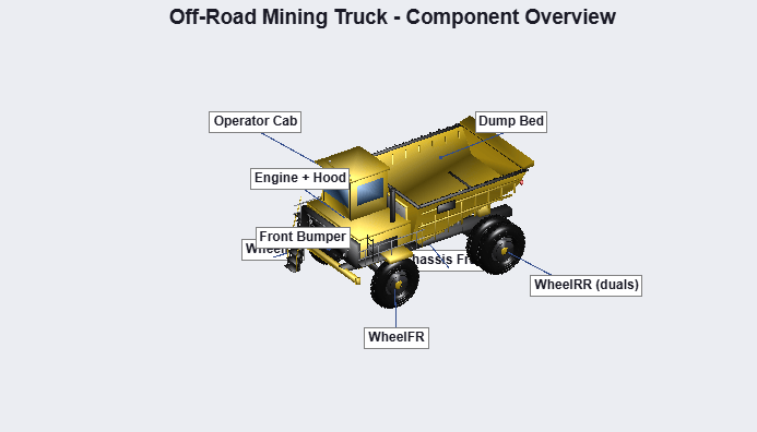
Annotate the major parts such as the chassis, wheels, cab, dump bed, and hydraulic cylinders by using the helperShowMiningTruckPartNames helper function.
helperShowMiningTruckPartNames(truckMesh,dim)
Build Rigid Body Tree from Asset
The 3D asset is organized into six rigid bodies, so it maps directly onto a rigidBodyTree (Robotics System Toolbox) model: the chassis becomes the base, and the other five bodies attach to it as jointed rigidBody (Robotics System Toolbox) objects. Build the rigid body tree by using the helperBuildMiningTruckRBT helper function. The helper function extracts each top-level mesh from truckScene, writes it to a per-part Collada (.dae) file, and assembles a rigidBodyTree. The dump bed and four wheels attach to the chassis via revolute joints placed at their physical pivot axes. The dump bed pivots about the its tilt axis and each wheel spins about its axle.
[truckRBT,partsDir] = helperBuildMiningTruckRBT(truckScene,dim);
Print the kinematic tree by using the showdetails (Robotics System Toolbox) object function. Each non-base body lists its joint name, joint type, axis, and parent body.
showdetails(truckRBT)
--------------------
Robot: (5 bodies)

 Idx      Body Name         Joint Name         Joint Type      Parent Name(Idx)   Children Name(s)
 ---      ---------         ----------         ----------      ----------------   ----------------
   1            Bed           BedHoist           revolute               base(0)
   2        WheelFR        WheelFRSpin           revolute               base(0)
   3        WheelFL        WheelFLSpin           revolute               base(0)
   4        WheelRR        WheelRRSpin           revolute               base(0)
   5        WheelRL        WheelRLSpin           revolute               base(0)
--------------------
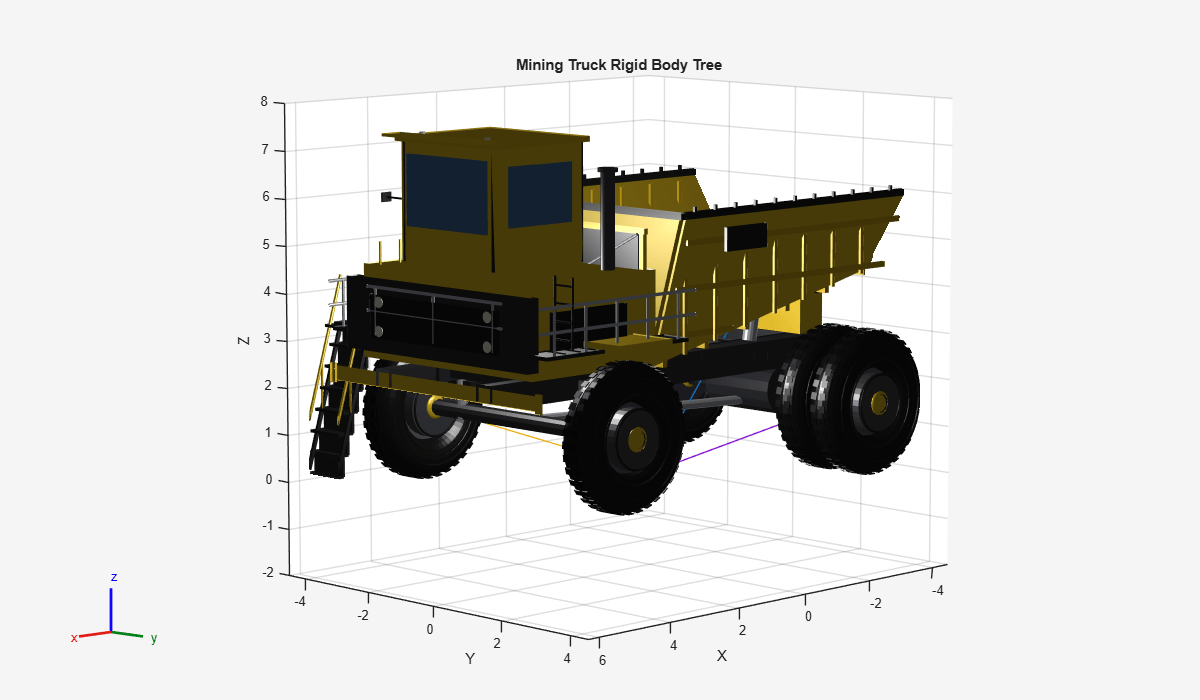
Visualize the rigid body tree of the truck. The joint configuration angles are all at their default value of zero, which corresponds to a lowered bed and wheels in their starting position.
figure(Name="Mining Truck Rigid Body Tree",Position=[100 100 1200 700])
show(truckRBT,Visuals="on",Collisions="off",Frames="on")
zlim([-2 8])
title("Mining Truck Rigid Body Tree")
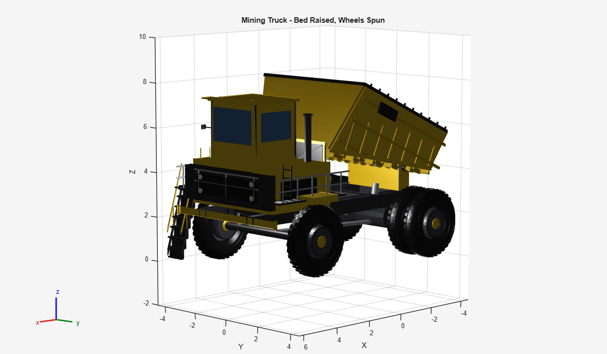
Visualize the truck in a specific configuration using the show (Robotics System Toolbox) object function. Tilt the bed up 25 degrees and spin the wheels 90 degrees forward.
config = [deg2rad(25) deg2rad(90) deg2rad(90) deg2rad(90) deg2rad(90)]; % [bed-hydraulics angle, four wheel-spin joint angles]
figure(Name="Mining Truck - Posed",Position=[100 100 1200 700])
show(truckRBT,config,Visuals="on",Collisions="off",Frames="off")
zlim([-2 10])
title("Mining Truck - Bed Raised, Wheels Spun")
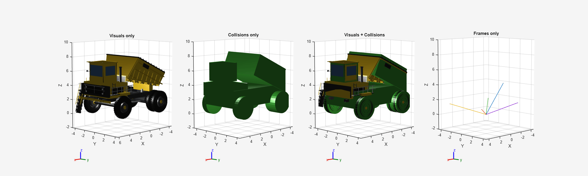
Each rigid body also carries a convex collision primitive such as a bounding box for the chassis and bed, and a cylinder per wheel sized to envelope the dual rears as one shape. These conservative bounding volumes are much cheaper to evaluate than the underlying meshes, making them well suited for checkCollision (Robotics System Toolbox) or downstream path-planning components. Compare the visuals and collisions side-by-side by calling show with different combinations of the Visuals and Collisions name-value arguments.
figure(Name="Mining Truck - Visuals vs Collisions",Position=[100 100 2000 600])
subplot(1,4,1)
show(truckRBT,config,Visuals="on",Collisions="off",Frames="off")
zlim([-2 10])
title("Visuals only")
subplot(1,4,2)
show(truckRBT,config,Visuals="off",Collisions="on",Frames="off")
zlim([-2 10])
title("Collisions only")
subplot(1,4,3)
show(truckRBT,config,Visuals="on",Collisions="on",Frames="off")
zlim([-2 10])
title("Visuals + Collisions")
subplot(1,4,4)
show(truckRBT,config,Visuals="off",Collisions="off",Frames="on")
zlim([-2 10])
title("Frames only")
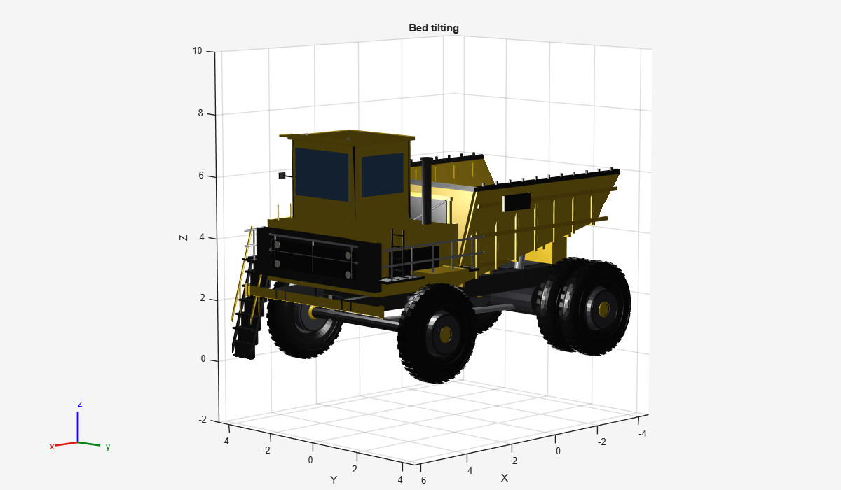
Animate the Truck
Animate the joints by using the helperAnimateMiningTruck helper function. The wheels first spin about their axles, and then the dump bed tilts up and back down. The chassis is the fixed base of the tree, so the truck articulates in place rather than moving across the scene.
helperAnimateMiningTruck(truckRBT)
Export to File
To use the constructed asset in downstream applications such as simulation engines or game engines, export it to a standard 3D file format. Save the hierarchical scene to a GLB file by using the asset3d.write function. The GLB format preserves the scene-graph hierarchy, materials, and node names in a single binary file.
outputDir = fullfile(pwd,"meshes");
if ~isfolder(outputDir)
    mkdir(outputDir)
end
glbPath = fullfile(outputDir,"off_road_mining_truck.glb");
asset3d.write(truckScene,glbPath)
Summary
In this example, you constructed a hierarchical 3D asset of an off-road mining truck using primitive shapes. You built one wheel at the origin, merged it into a single mesh, translated it to each axle position, and used a subsystem helper function to assemble the chassis, dump bed, and hydraulic cylinders. You organized the parts into six top-level rigid bodies in a scene graph such that the downstream applications can pivot the bed about its tilt axis and spin each wheel independently, while the dual rear tires on each side automatically move as one. You built a rigidBodyTree model from the asset and animated its wheel-spin and bed-tilt joints, and you exported the assembled model to a GLB file for off-road robotics simulation.

