主要内容

digitalFilter

Digital filter

Description

Use a digitalFilter object to store digital filter coefficients and, if available, filter design specifications. You can use the object to analyze the filter response and to filter signals.

  • Use filter in the form dataOut = filter(d,dataIn) to filter a signal with a digitalFilter object d. You can also use the filtfilt and fftfilt functions with digitalFilter objects. For a complete list of functions that you can use with digitalFilter objects, see Object Functions.

  • Use Filter Analyzer to visualize a digitalFilter object.

  • Use Filter Designer to import and modify a digitalFilter object.

Creation

Create digitalFilter objects that contain coefficients representing Cascaded Transfer Functions (CTF). (since R2026a)

Note

To create a digitalFilter object with design specifications, use designfilt or the Filter Designer app.

  • Use the syntax d = designfilt(response,Name=Value) to design a digital filter d with response type response and design specifications listed as name-value arguments.

  • Use the syntax designfilt(d) or Filter Designer to edit an existing filter, d. The filter properties are otherwise read-only.

Description

d = digitalFilter(B,A) creates a digital filter d with CTF numerator coefficients B and CTF denominator coefficients A. The filter uses normalized frequencies.

d = digitalFilter(B,A,g) specifies the scale values, g, across filter sections.

d = digitalFilter(___,SampleRate=Fs) sets a sample rate Fs to the filter for any of the previous syntaxes.

example

Input Arguments

expand all

Cascaded transfer function (CTF) coefficients, specified as scalars, vectors, or matrices. B and A list the numerator and denominator coefficients of the cascaded transfer function, respectively.

B must be of size L-by-(m + 1) and A must be of size L-by-(n + 1), where:

  • L represents the number of filter sections.

  • m represents the order of the filter numerators.

  • n represents the order of the filter denominators.

For more information about the cascaded transfer function format and coefficient matrices, see Specify Digital Filters in CTF Format.

Note

If any element of A(:,1) is not equal to 1, then digitalFilter normalizes the filter coefficients by A(:,1). In this case, A(:,1) must be nonzero.

Data Types: double
Complex Number Support: Yes

Scale values, specified as a real-valued scalar or as a real-valued vector with L + 1 elements, where L is the number of CTF sections. The scale values represent the distribution of the filter gain across the sections of the cascaded filter representation.

The digitalFilter function applies a gain to the filter sections using the scaleFilterSections function depending on how you specify g:

  • Scalar — The function distributes the gain uniformly across all filter sections.

  • Vector — The function applies the first L gain values to the corresponding filter sections and distributes the last gain value uniformly across all filter sections.

Data Types: double

Sample rate of the digital filter, specified as one of these:

  • "normalized"digitalFilter sets the digital filter d to use normalized frequency.

  • Positive scalar — digitalFilter sets the sample rate of the digital filter d to Fs Hz.

Data Types: char | string | single | double

Properties

expand all

A digitalFilter object can have sets of properties that depend on how you create the object and whether the object represents a single-stage digital filter or a cascade of digital filters (digital filter cascade). All properties are read-only.

  • If the digitalFilter object represents a single-stage digital filter, including coefficients in CTF format, then the object has Coefficients properties.

  • If the digitalFilter object represents a digital filter cascade, then the object has Stages properties. (since R2026a)

  • If the digitalFilter object has design specifications, then the object has Specifications properties.

Coefficients

Numerator coefficients, returned as a row vector or as an L-by-(m + 1) matrix, where L is the number of CTF sections and m is the numerator order. See Return Digital Filters in CTF Format for more information.

Denominator coefficients, returned as 1, a row vector, or an L-by-(n + 1) matrix, where L is the number of CTF sections and n is the denominator order. See Return Digital Filters in CTF Format for more information.

Stages

Since R2026a

Filter stages, returned as digitalFilter objects. Each digitalFilter object represents a stage of a digital filter cascade. A stage can consist of one or more substages.

Specifications

The Specification properties returned in a digitalFilter object depend on the filter response and design specified when creating the object using designfilt. All properties are read-only.

Filter response type, returned as one of the values listed in the table.

ValueDescriptionRequires DSP System Toolbox™ License
'lowpass'Lowpass filter 
'highpass'Highpass filter 
'bandpass'Bandpass filter 
'bandstop'Bandstop filter 
'differentiator'FIR differentiator filter 
'hilbert'FIR Hilbert transformer filter 
'arbmag'Filter of arbitrary-magnitude response 
'arbmagnphase'Filter of arbitrary magnitude and phase responses
'arbgrpdelay'IIR filter of arbitrary group delay
'fracdelay'FIR filter of fractional delay
'isinclp'Inverse sinc lowpass FIR filter
'isinchp'Inverse sinc highpass FIR filter
'notch'Multi-notch IIR filter
'peak'Multi-peak IIR filter
'complexlowpass'Complex FIR lowpass filter 
'complexhighpass'Complex FIR highpass filter 

Impulse response type, returned as 'fir' or 'iir'.

Since R2026a

Frequency normalization status, returned as one of these:

  • 1 (true) — The digitalFilter object works with normalized frequencies.

  • 0 (false) — The digitalFilter object uses a sample rate in Hz, which is returned in the SampleRate property.

Sample rate, returned as a positive scalar expressed in hertz.

This property is visible only if NormalizedFrequency is false. (since R2026a)

A digitalFilter object can have more properties that describe its filter design. For more information about filter design properties, see Frequency Constraints, Filter Order, Magnitude Constraints, and Design Method.

Object Functions

expand all

fftfiltFFT-based FIR filtering using overlap-add method
filter1-D digital filter
filtfiltZero-phase digital filtering
bandpassBandpass-filter signals
bandstopBandstop-filter signals
highpassHighpass-filter signals
lowpassLowpass-filter signals
freqzFrequency response of digital filter
grpdelayAverage filter delay (group delay)
impzImpulse response of digital filter
impzlengthImpulse response length
phasedelayPhase delay of digital filter
phasezPhase response of digital filter
stepzStep response of digital filter
zerophaseZero-phase response of digital filter
zplaneZero-pole plot for discrete-time systems
filtordFilter order
firtypeType of linear phase FIR filter
getNumStagesGet number of stages in digital filter cascade
infoInformation about digital filter
isallpassDetermine whether filter is allpass
isdoubleDetermine if digital filter coefficients are double precision
isfirDetermine if digital filter has finite impulse response
islinphaseDetermine whether filter has linear phase
ismaxphaseDetermine whether filter is maximum phase
isminphaseDetermine whether filter is minimum phase
issingleDetermine if digital filter coefficients are single precision
isstableDetermine whether filter is stable
doubleCast coefficients of digital filter to double precision
singleCast coefficients of digital filter to single precision
cascadeCascade of filter system objects
ctfConvert digital filter to coefficients in cascaded transfer function format
ssConvert digital filter to state-space representation
tfConvert digital filter to transfer function
zpkConvert digital filter to zero-pole-gain representation
filt2blockGenerate Simulink filter block
setSampleRateSet sample rate of digital filter
toMultirateCreate multirate filter System object from digital FIR filter object

Examples

collapse all

Design a lowpass IIR filter with order 8, passband frequency 35 kHz, and passband ripple 0.2 dB. Specify a sample rate of 200 kHz. Visualize the frequency response of the filter.

lpFilt = designfilt("lowpassiir",FilterOrder=8, ...
         PassbandFrequency=35e3,PassbandRipple=0.2, ...
         SampleRate=200e3);
freqz(lpFilt)

Figure contains 2 axes objects. Axes object 1 with title Phase, xlabel Normalized Frequency (\times\pi rad/sample), ylabel Phase (degrees) contains an object of type line. Axes object 2 with title Magnitude, xlabel Normalized Frequency (\times\pi rad/sample), ylabel Magnitude (dB) contains an object of type line.

Use the filter you designed to filter a 1000-sample random signal.

dataIn = randn(1000,1);
dataOut = filter(lpFilt,dataIn);

Output the filter coefficients, expressed as cascaded transfer functions.

ctfNum = lpFilt.Numerator
ctfNum = 4×3

    0.2666    0.5333    0.2666
    0.1943    0.3886    0.1943
    0.1012    0.2023    0.1012
    0.0318    0.0636    0.0318

ctfDen = lpFilt.Denominator
ctfDen = 4×3

    1.0000   -0.8346    0.9073
    1.0000   -0.9586    0.7403
    1.0000   -1.1912    0.5983
    1.0000   -1.3810    0.5090

Since R2026a

Design bandpass IIR digital filters and filter a sinusoidal signal with harmonics.

Design a 10th-order bandpass IIR elliptic filter with passband edge frequencies of [0.3, 0.5] radians/sample, passband ripple of 0.1 dB, and stopband attenuation of 50 dB. Obtain the filter coefficients in CTF format.

N = 10;
Rp = 0.1;
Rs = 50;
Wp = [0.3 0.5];
[B,A] = ellip(N/2,Rp,Rs,Wp,"bandpass","ctf");

Create a digital filter object from the filter coefficients. Set the sample rate to 1000 Hz.

Fs = 1000;
dCoeff = digitalFilter(B,A,SampleRate=Fs);

Create a digital filter object from the filter specifications.

dSpecs = designfilt("bandpassiir",SampleRate=Fs, ...
    FilterOrder=N,DesignMethod="ellip", ...
    PassbandFrequency1=Wp(1)*Fs/2,PassbandFrequency2=Wp(2)*Fs/2, ...
    StopbandAttenuation1=Rs,PassbandRipple=Rp,StopbandAttenuation2=Rs);

Generate a sinusoidal signal with an amplitude of 1 V and a frequency of 60 Hz, and add third-, fifth-, and seventh-order harmonics. The harmonic amplitudes are 1 V, 0.2 V, and 0.1 V, respectively. Sample the signal for 1 second.

rng("default")
a = [1 1 0.2 0.1];
f = 60*[1 3 5 7];
t = (0:1/Fs:1)';
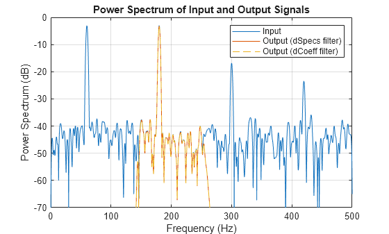
x = cos(2*pi*f.*t)*a' + 0.1*randn(size(t));

Filter the signal using the digitalFilter objects created from specifications and from CTF coefficients. Compare the input and output signals.

ySpecs = filtfilt(dSpecs,x);
yCoeff = filtfilt(dCoeff,x);

pspectrum([x ySpecs yCoeff],Fs)
title("Power Spectrum of Input and Output Signals")
legend(["Input" "Output (dSpecs filter)" "Output (dCoeff filter)"])
set(gca().Children(1),LineStyle="--")
ylim([-70 0])

Figure contains an axes object. The axes object with title Power Spectrum of Input and Output Signals, xlabel Frequency (Hz), ylabel Power Spectrum (dB) contains 3 objects of type line. These objects represent Input, Output (dSpecs filter), Output (dCoeff filter).

More About

expand all

References

[1] Lyons, Richard G. Understanding Digital Signal Processing. Upper Saddle River, NJ: Prentice Hall, 2004.

Version History

Introduced in R2014a

expand all

See Also

Live Editor Tasks

Apps

Objects

Functions