电驱动装置
利用这些示例了解如何对异步、同步、开关磁阻电机和控制进行建模。
精选示例
Visualize Four-Quadrant Operation of Electric Drive System
Helps you visualize the torque-speed trajectory of a Motor & Drive (System Level) block operated in all four quadrants.

Design PID Control for DC Motor Using Classical Control Theory
Design a PID controller for a DC Motor using classical control theory. Alternatively, you can use Steady State Manager, Model Linearizer, Frequency Response Estimator, or PID tuner apps to streamline the design.
Classify Motor Faults Using Deep Learning
Train a deep learning model to classify faults in a permanent magnet synchronous motor (PMSM) using simulated data across various revolutions per minute (RPM). You use Simscape Electrical™ to create the model for a fault scenario, then use Deep Learning Toolbox™ to train a neural network to classify the fault data.

控制带开放端绕组的三相 PMSM 的速度
此示例展示了如何控制带开放端绕组的内置式永磁同步电机 (IPMSM) 中的转子角转速。高压电池通过两个受控三相转换器为 IPMSM 供电。IPMSM 根据负载以电机模式和发电模式运行。理想转矩源提供负载。Scopes 子系统包含示波器,可用于查看仿真结果。Control 子系统包含一个基于 PI 的磁场定向控制结构。在时长一秒的仿真过程中,角速度需求为 0 rpm、500 rpm、2000 rpm,然后是 3000 rpm。
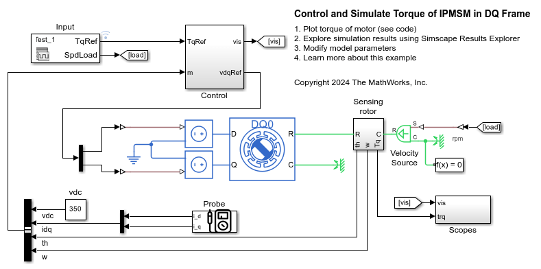
Control and Simulate Torque of IPMSM in DQ Frame
Control the torque in an automotive electrical traction drive of an interior permanent magnet synchronous machine (IPMSM). The example controls and simulates the torque in the rotor direct-quadrature (DQ) reference frame. You can use the DQ reference frame to design the controller and to speed up the simulation. The IPMSM operates in both motoring and generating modes according to the load. An ideal angular velocity source provides the load. The Control subsystem uses an open-loop approach to control the IPMSM torque and a closed-loop approach to control the current. The control algorithm converts the torque request to the relevant current references. The reference DQ voltages feed the IPMSM. The simulation involves several torque steps in both motor and generator modes.
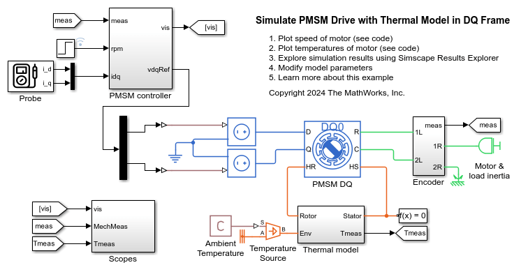
在 DQ 参考系中对包含热模型的三相 PMSM 驱动进行仿真
此示例展示了如何在直轴-交轴 (DQ) 参考系中对永磁同步电机 (PMSM) 进行仿真。该 PMSM 包含热模型和经验铁损。要设计 PMSM 控制器并实现所需性能,请选择模型的架构和增益。定子和转子的初始温度为 25 摄氏度。环境温度为 27 摄氏度。Scopes 子系统包含示波器,可用于查看仿真结果。
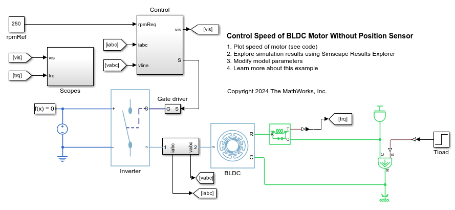
无位置传感器时 BLDC 电机的转速控制
此示例展示了如何在无位置传感器的情况下控制无刷直流 (BLDC) 电力驱动装置的转速。DC 电压源通过受控的三相逆变器为 BLDC 供电。Control 子系统实现无传感器转速控制策略。滞后控制器用于控制相电流。Scopes 子系统包含示波器,可用于查看仿真结果。
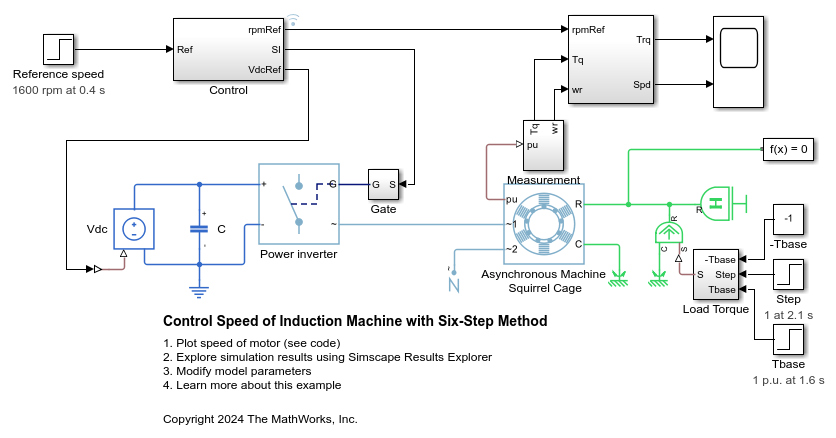
使用六步法控制感应电机的转速
此示例展示了如何使用标量六步控制方法控制异步电机 (ASM) 驱动装置中的转子转速。该控制算法将参考转速转换为参考频率。控制器根据参考频率生成栅极脉冲,同时保持恒定的电压频率比。
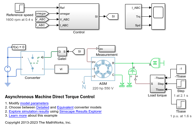
使用直接转矩控制法控制感应电机的转速
此示例展示了如何使用直接转矩控制方法控制异步电机 (ASM)。基于 PI 的转速控制器提供转矩参考值。直接转矩控制器生成逆变器脉冲。
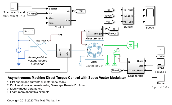
异步电机结合空间矢量调制器的直接转矩控制
此示例展示了如何使用结合空间矢量调制器的直接转矩控制方法控制异步电机 (ASM)。基于 PI 的转速控制器提供转矩参考值。直接转矩控制器生成空间矢量调制器所需的参考电压。DC 电压源通过受控的平均值电压源转换器为 ASM 供电。
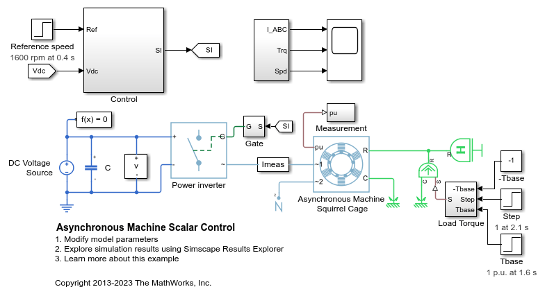
异步电机标量控制
此示例展示了如何使用标量 V/f 控制方法控制异步电机 (ASM) 驱动装置中的转子转速。转换器将参考转速转换为参考电频率。控制器通过标量 V/f 控制保持恒定的电压频率比,根据参考频率生成参考电压。
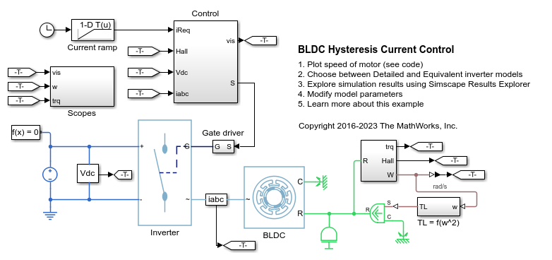
BLDC 滞后电流控制
此示例展示了如何使用滞后控制器控制基于 BLDC 的电力驱动装置中的电流。DC 电压源通过受控的三相逆变器为 BLDC 供电。向电机控制器提供一个电流请求斜坡信号。负载转矩与转子转速呈二次方关系。Control 子系统实现基于滞后的电流控制策略。Scopes 子系统包含示波器,可用于查看仿真结果。

BLDC 位置控制
此示例展示了如何控制基于 BLDC 的电力驱动装置中的转子角。理想转矩源提供负载。Control 子系统采用基于 PI 的级联控制结构,包含三个控制环:外层位置控制环、转速控制环和内层电流控制环。BLDC 由受控的三相逆变器供电。逆变器的栅极信号通过霍尔信号获得。仿真使用阶跃参考信号。Scopes 子系统包含示波器,可用于查看仿真结果。

BLDC 转速控制
此示例展示了如何控制基于 BLDC 的电力驱动装置中的转子转速。理想转矩源提供负载。Control 子系统采用基于 PI 的级联控制结构,包含一个外层转速控制环和一个内层 DC 链路电压控制环。DC 链路电压通过 DC-DC 降压转换器进行调整。BLDC 由受控的三相逆变器供电。逆变器的栅极信号通过霍尔信号获得。仿真使用转速阶跃信号。Scopes 子系统包含示波器,可用于查看仿真结果。
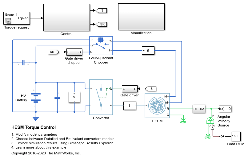
HESM 转矩控制
此示例展示了如何控制基于混合励磁同步电机 (HESM) 的电力牵引驱动装置中的转矩。HESM 由永磁体和励磁绕组励磁。高压电池通过受控三相转换器为 SM 定子绕组供电,通过受控四象限斩波器为 SM 转子绕组供电。理想角速度源提供负载。Control 子系统使用开环方法控制转矩,并使用闭环方法控制电流。在每个采样时刻,转矩请求都会转换为相关的参考电流。电流控制基于 PI。仿真在电机模式和发电机模式下都使用了多个转矩阶跃。Visualization 子系统包含示波器,可用于查看仿真结果。
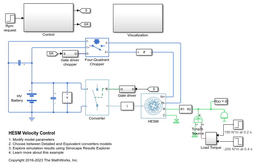
HESM 速度控制
此示例展示了如何控制基于混合励磁同步电机 (HESM) 的电力牵引驱动装置中的转子角转速。HESM 由永磁体和励磁绕组励磁。高压电池通过受控三相转换器为 HESM 定子绕组供电,通过受控四象限斩波器为 HESM 转子绕组供电。理想转矩源提供负载。Control 子系统包含基于 PI 的多速率级联控制结构。控制结构具有一个外层角速度控制环和三个内层电流控制环。Visualization 子系统包含示波器,可用于查看仿真结果。

IPMSM 转矩控制
此示例展示了如何控制基于内置式永磁同步电机 (IPMSM) 的汽车电力牵引驱动装置中的转矩。高压电池通过受控三相转换器为 IPMSM 供电。IPMSM 根据负载以电机模式和发电模式运行。理想角速度源提供负载。Control 子系统使用开环方法控制 IPMSM 转矩,并使用闭环方法控制电流。在每个采样时刻,转矩请求都会转换为相关的参考电流。电流控制基于 PI,并且其使用的采样率比转矩控制所用的采样率更快。仿真在电机模式和发电机模式下都使用了多个转矩阶跃。任务调度是在 Stateflow® 中设计的。Scopes 子系统包含示波器,可用于查看仿真结果。
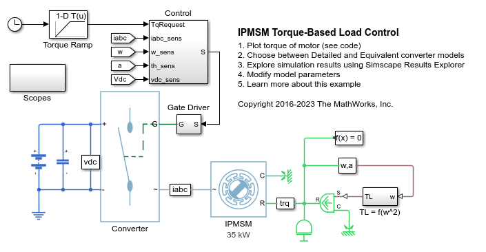
基于 IPMSM 转矩的负载控制
此示例展示了如何控制基于内置式永磁同步电机 (IPMSM) 的驱动装置中的转矩。高压电池通过受控三相逆变器为 IPMSM 供电。向电机控制器提供一个转矩请求斜坡信号。负载转矩与转子转速呈二次方关系。Control 子系统使用开环方法控制 IPMSM 转矩,并使用闭环方法控制电流。在每个采样时刻,转矩请求都会转换为相关的参考电流。电流控制基于 PI,并且其使用的采样率比转矩控制所用的采样率更快。任务调度是在 Stateflow® 中设计的。Scopes 子系统包含示波器,可用于查看仿真结果。
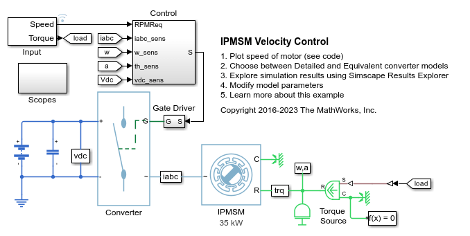
IPMSM 速度控制
此示例展示了如何控制基于内置式永磁同步电机 (IPMSM) 的汽车电力牵引驱动装置中的转子角转速。高压电池通过受控三相转换器为 IPMSM 供电。IPMSM 根据负载以电机模式和发电模式运行。理想转矩源提供负载。Scopes 子系统包含示波器,可用于查看仿真结果。Control 子系统包含基于 PI 的多速率级联控制结构,该结构具有一个外层角速度控制环和两个内层电流控制环。Control 子系统中的任务调度以 Stateflow® 状态机的形式实现。在时长一秒的仿真过程中,角速度需求为 0 rpm、500 rpm、2000 rpm,然后是 3000 rpm。
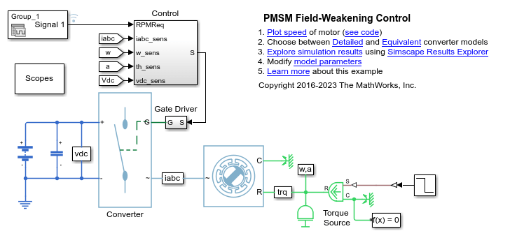
PMSM 弱磁控制
此示例展示了如何控制基于永磁同步电机 (PMSM) 的电力牵引驱动装置中高于标称速度的转子角速度。高压电池通过受控三相转换器为 PMSM 供电。Control 子系统包含基于 PI 的多速率级联控制结构,该结构具有一个外层角速度控制环和两个内层电流控制环。速度控制器生成参考转矩。零 d 轴控制器将此参考转矩转换为参考电流。弱磁控制器调整参考电流,以在超出额定转速时满足电压约束。Stateflow® 状态机在 Control 子系统中实现任务调度。在 0.7 秒的仿真过程中,角速度需求从 0 rpm 逐渐增大至 4000 rpm。Scopes 子系统包含示波器,可用于查看仿真结果。
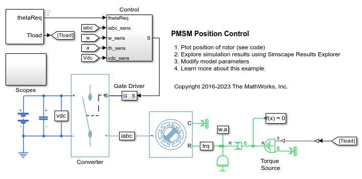
PMSM 位置控制
此示例展示了如何控制基于 PMSM 的电力驱动装置中的转子位置。理想转矩源提供负载。Control 子系统采用级联控制结构,包含两个控制环:一个外层位置和转速控制环和一个内层电流控制环。用于估计器设计的状态包括电磁转矩、机械角速度、机械角位置和扰动(负载转矩)。最佳状态反馈线性二次调节器用于控制位置和转速。龙伯格观测器用于估计负载。PI 控制器实现内层电流控制环。通过受控三相逆变器为 PMSM 供电。仿真使用阶跃参考信号。Scopes 子系统包含示波器,可用于查看仿真结果。

SM 转矩控制
此示例展示了如何控制基于同步电机 (SM) 的电力牵引驱动装置中的转矩。高压电池通过受控三相转换器为 SM 定子绕组供电,通过受控四象限斩波器为 SM 转子绕组供电。理想角速度源提供负载。Control 子系统使用开环方法控制转矩,并使用闭环方法控制电流。在每个采样时刻,转矩请求都会转换为相关的参考电流。电流控制基于 PI。仿真在电机模式和发电机模式下都使用了多个转矩阶跃。任务调度以 Stateflow® 状态机的形式实现。Visualization 子系统包含示波器,可用于查看仿真结果。
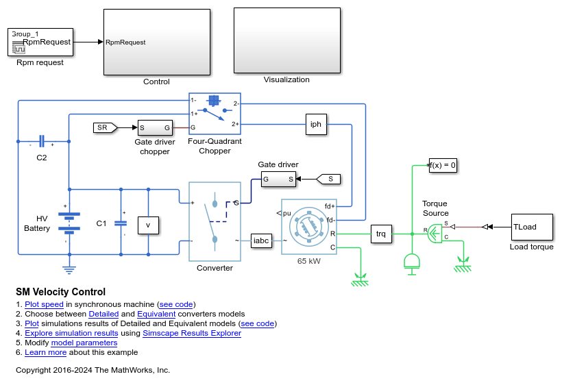
SM 速度控制
此示例展示了如何控制基于同步电机 (SM) 的电力牵引驱动装置中的转子角转速。高压电池通过受控三相转换器为 SM 定子绕组供电,通过受控四象限斩波器为 SM 转子绕组供电。理想转矩源提供负载。Control 子系统包含基于 PI 的多速率级联控制结构,该结构具有一个外层角速度控制环和三个内层电流控制环。Control 子系统中的任务调度以 Stateflow® 状态机的形式实现。Visualization 子系统包含示波器,可用于查看仿真结果。
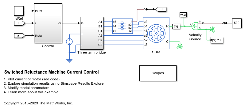
开关磁阻电机电流控制
此示例展示了如何控制基于开关磁阻电机 (SRM) 的电力驱动装置中的电流振幅。DC 电压源通过受控三臂桥为 SRM 供电。理想角速度源提供负载。转换器的导通和关断角度保持恒定。基于 PI 的电流控制器调节电流振幅。
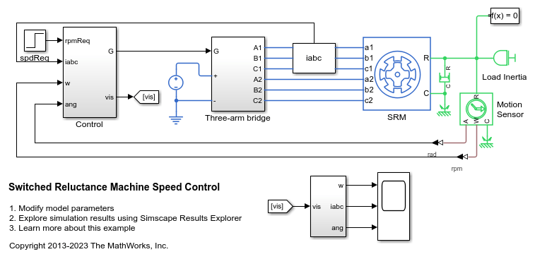
控制开关磁阻电机的转子转速
此示例展示了如何控制基于开关磁阻电机 (SRM) 的电力驱动装置中的转子转速。DC 电压源通过受控三臂桥为 SRM 供电。为了实现正向和反向旋转,此示例使用转速误差来调整转换器的导通和关断角度。
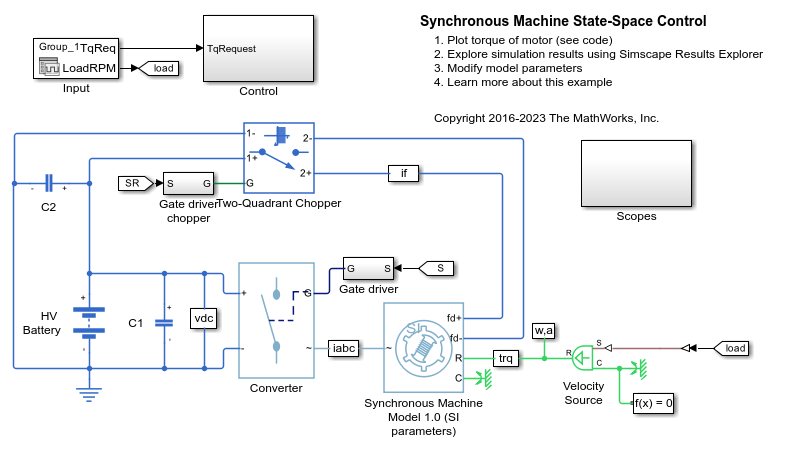
同步电机状态空间控制
此示例展示了如何使用状态空间控制来控制基于同步电机 (SM) 的电力牵引驱动装置中的电流。高压电池通过受控三相转换器为 SM 定子绕组供电,通过受控两象限斩波器为 SM 转子绕组供电。理想角速度源提供负载。SM 的运行转速低于基转速。在每个采样时刻,转矩请求都会通过零 d 轴控制方法转换为相关的参考电流。状态反馈控制器控制转子参考系中的电流。龙伯格观测器获取速度相关前馈预控制项。仿真在电机模式和发电机模式下都使用了多个转矩阶跃。任务调度以 Stateflow® 状态机的形式实现。Scopes 子系统包含示波器,可用于查看仿真结果。
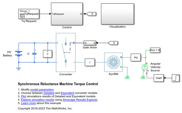
同步磁阻电机转矩控制
此示例展示了如何控制基于同步磁阻电机 (SynRM) 的电力驱动装置中的转矩。高压电池通过受控三相转换器为 SynRM 供电。理想角速度源提供负载。Control 子系统使用开环方法控制转矩,并使用闭环方法控制电流。在每个采样时刻,都会使用最大转矩电流比策略将转矩请求转换为相关的参考电流。电流控制基于 PI。仿真在电机模式和发电机模式下都使用了转矩阶跃。Visualization 子系统包含示波器,可用于查看仿真结果。
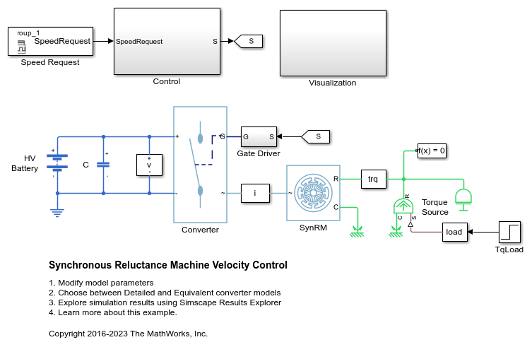
同步磁阻电机速度控制
此示例展示了如何控制基于同步磁阻电机 (SynRM) 的电力驱动装置中的转子角速度。高压电池通过受控三相转换器为 SynRM 供电。理想转矩源提供负载。Control 子系统包含基于 PI 的多速率级联控制结构。控制结构具有一个外层角速度控制环和两个内层电流控制环。Visualization 子系统包含示波器,可用于查看仿真结果。
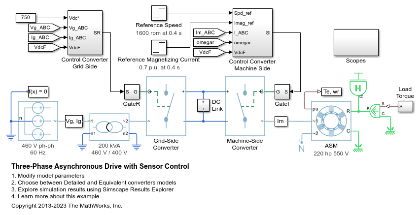
带传感器控制的三相异步驱动
此示例展示了如何使用带传感器转子磁场定向控制来控制和分析异步电机 (ASM) 的运行。该模型展示了主电路,以及包含控制、测量和示波器的三个附加子系统。Controls 子系统包含两个控制器:一个用于电网侧转换器 (AC/DC),另一个用于电机侧转换器 (DC/AC)。Scopes 子系统包含两个示波器:一个用于电网侧转换器,另一个用于 ASM。执行该模型时,频谱分析仪会打开并显示 A 相电源电流的频率数据。
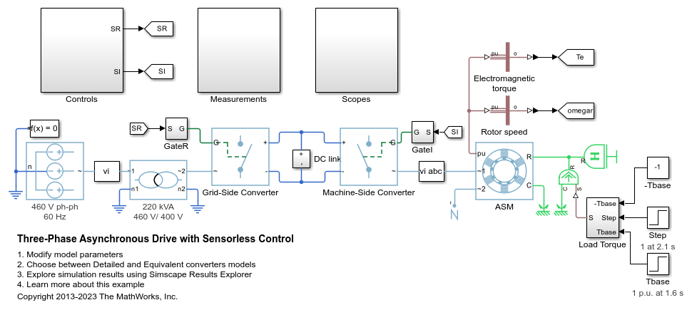
无传感器控制的三相异步驱动
此示例展示了如何使用无传感器转子磁场定向控制来控制和分析异步电机 (ASM) 的运行。该模型展示了主电路,以及包含控制、测量和示波器的三个附加子系统。Controls 子系统包含两个控制器:一个用于电网侧转换器 (AC/DC),另一个用于电机侧转换器 (DC/AC)。Scopes 子系统包含两个示波器:一个用于电网侧转换器,另一个用于 ASM。执行该模型时,频谱分析仪会打开并显示 A 相电源电流的频率数据。
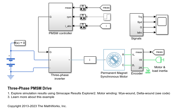
三相 PMSM 驱动建模
此示例展示了一个采用星型绕组和三角型绕组配置的永磁同步电机 (PMSM),以及一个适用于典型混合动力车辆的逆变器。该逆变器直接连接到车辆电池,但您也可以在两者之间实现一个 DC-DC 转换器阶段。使用该模型,通过选择架构和增益来设计 PMSM 控制器,从而实现期望的性能。为了检查 IGBT 开通和关断时序,请使用更详细的 N-Channel IGBT 模块替换 IGBT 器件。对于整车建模,请使用 Motor & Drive (System Level) 模块,以基于能量的模型来抽象 PMSM、逆变器和控制器。
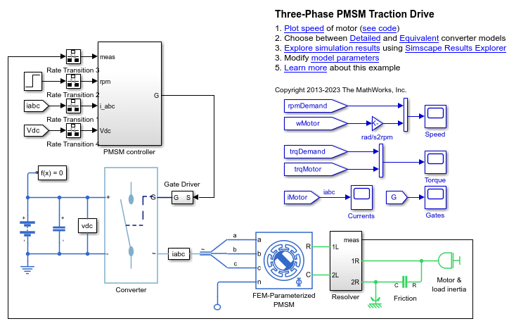
三相 PMSM 牵引驱动
此示例展示了如何控制基于永磁同步电机 (PMSM) 的电力牵引驱动装置中的转子转速。高压电池通过受控三相转换器为 FEM 参数化的 PMSM 模块供电。Rotational Friction 模块提供负载。位置和转速信息通过高保真旋转变压器获得。PMSM controller 子系统包含一个级联控制结构,该结构具有一个外层转速控制环和两个内层电流控制环。在 0.25 秒的仿真过程中,转子转速需求从 0 rpm 斜坡上升至 1000 rpm。
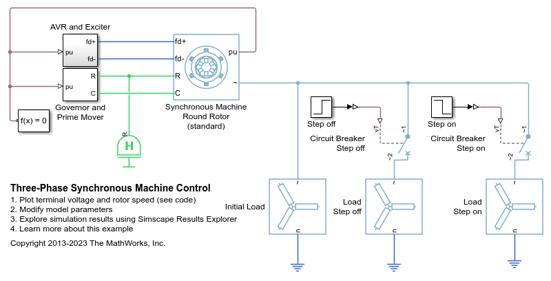
三相同步电机控制
此示例展示了如何控制和初始化同步电机 (SM)。测试电路显示 SM 作为发电机运行。端电压通过 AVR 控制,转速通过调速器控制。
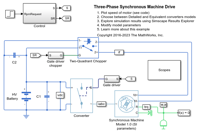
三相同步电机驱动装置
此示例展示了如何控制基于同步电机 (SM) 的电力驱动装置中的转子转速。高压电池通过受控三相转换器为 SM 定子绕组供电,通过受控两象限斩波器为 SM 转子绕组供电。可以使用该模型来设计 SM 控制器,通过选择架构和增益实现期望的性能。Scopes 子系统包含示波器,可用于查看仿真结果。
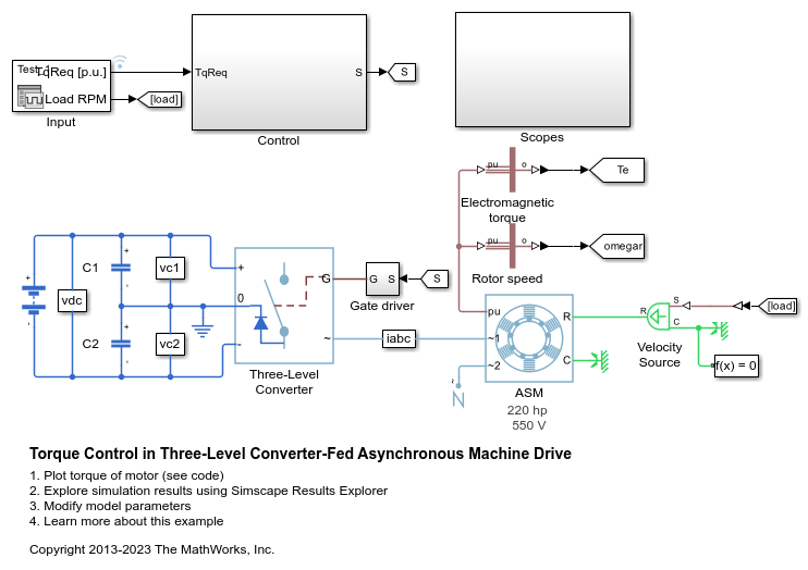
三电平转换器供电异步电机驱动装置中的转矩控制
此示例展示了如何控制基于异步电机 (ASM) 的电力牵引驱动装置中的转矩。高压电池通过三相三电平中性点钳位受控转换器为 ASM 供电。ASM 以电机模式和发电模式运行。理想角速度源提供负载。Control 子系统使用磁场定向控制策略来控制磁通和转矩。电流控制基于 PI。比例控制器调节中性点电压。仿真在电机模式和发电机模式下都使用了多个转矩阶跃。Scopes 子系统包含示波器,可用于查看仿真结果。

单相异步电机直接转矩控制
此示例展示了如何使用直接转矩控制来控制基于单相异步电机 (ASM) 的电力驱动装置中的转子转速。理想转矩源提供负载。Control 子系统采用级联控制结构。基于 PI 的外层转速控制环为来自内层环的直接转矩控制算法提供参考转矩和参考磁通。单相 ASM 由 H 桥供电。Scopes 子系统包含示波器,可用于查看仿真结果。
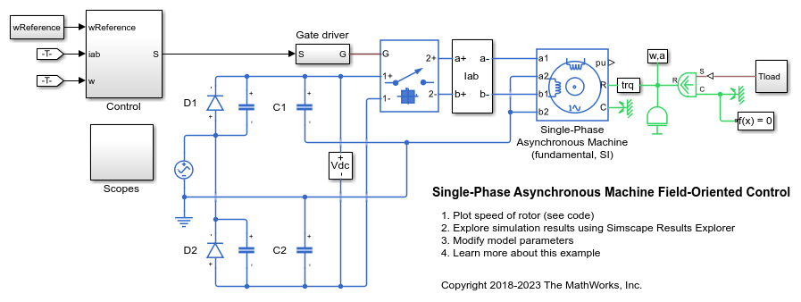
单相异步电机磁场定向控制
此示例展示了如何使用磁场定向控制来控制基于单相异步电机 (ASM) 的电力驱动装置中的转子转速。理想转矩源提供负载。Control 子系统采用基于 PI 的级联控制结构,包含一个外层转速控制环和两个内层电流控制环。单相 ASM 由 H 桥供电。Scopes 子系统包含示波器,可用于查看仿真结果。
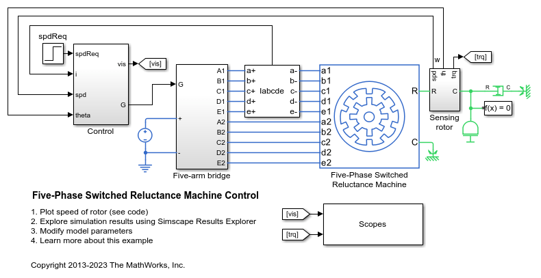
五相开关磁阻电机控制
此示例展示了如何控制基于五相开关磁阻电机 (SRM) 的电力驱动装置中的转子转速。DC 电压源通过受控五臂桥为 SRM 供电。转换器的导通和关断角度保持恒定。

四相开关磁阻电机控制
此示例展示了如何控制基于四相开关磁阻电机 (SRM) 的电力驱动装置中的转子转速。DC 电压源通过受控四臂桥为 SRM 供电。转换器的导通和关断角度保持恒定。
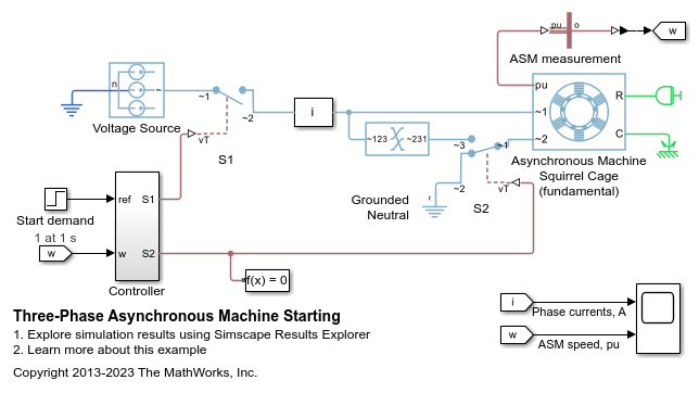
三相异步电机启动
此示例展示了如何对感应电机的星型-三角型启动电路进行建模。一秒钟后,Controller 子系统闭合标注为 S1 的开关。该开关闭合后,电源便连接到电机。最初,电机以星型配置连接到电源,因为标注为 S2 的开关将 ~1 端口的每相连接到 ~2 端口的对应相,而 ~3 端口则保持未连接状态。当电机转速达到同步转速的 80% 时,S2 通过断开 ~2 端口的每相,并将 ~1 端口的每相连接到 ~3 端口的对应相,以三角型配置重新连接电机。此后,无论转子转速如何,电机都将以三角型配置运行。电机采用星型配置时,电源侧看到的阻抗较高,从而降低启动电流,并减少对其他连接负载的干扰。
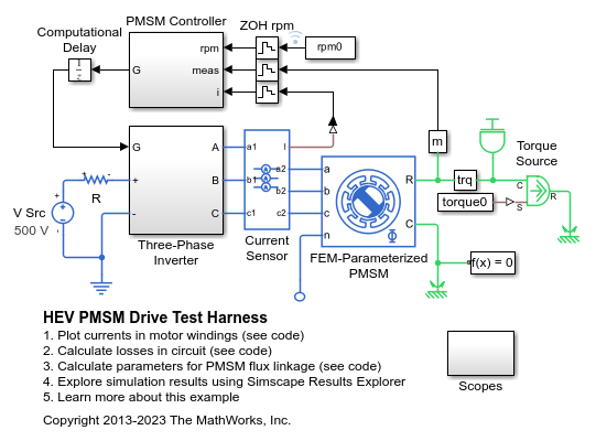
HEV PMSM 驱动测试框架
此示例展示了一个适用于典型混合动力车辆的永磁同步电机 (PMSM) 驱动测试框架。该测试框架可用于确定在给定转速和转矩下运行时的总驱动损耗。然后,Simscape™ Electrical™ Motor & Drive (System Level) 模块可以使用此测试框架提供的损耗信息表来对完整的驱动周期进行快速仿真,同时仍然准确预测整体系统效率。
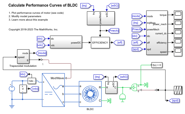
计算 BLDC 的性能曲线
此示例展示了如何计算无刷 DC (BLDC) 电机的性能曲线。仿真包含一个速度斜坡。使用理想梯形调制波来驱动平均值转换器。使用触发子系统来确定给定速度下的峰值转矩、功率、电流和效率值。

单相 PMSM 控制
此示例展示了如何控制单相永磁同步电机 (SPPMSM) 驱动装置中的转子转速。DC 电压源通过受控 H 桥为 SPPMSM 供电。Control 子系统实现转速控制策略。
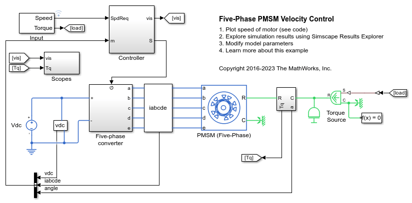
五相 PMSM 速度控制
此示例展示了如何控制基于五相永磁同步电机 (PMSM) 的电力牵引驱动装置中的转子角速度。DC 电压源通过受控五相转换器为 PMSM 供电。PMSM 根据负载以电机模式和发电模式运行。理想转矩源提供负载。Scopes 子系统包含示波器,可用于查看仿真结果。Control 子系统包含基于 PI 的级联控制结构,该结构具有一个外层角速度控制环和四个内层电流控制环。在时长一秒的仿真过程中,角速度需求为 0 rpm、500 rpm、2000 rpm,然后是 3000 rpm。
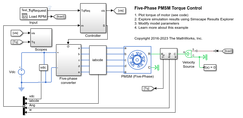
五相 PMSM 转矩控制
此示例展示了如何控制基于五相永磁同步电机 (PMSM) 的电力牵引驱动装置中的转矩。DC 电压源通过受控五相转换器为 PMSM 供电。PMSM 根据负载以电机模式和发电模式运行。理想角速度源提供负载。Control 子系统使用开环方法控制 PMSM 转矩,并使用闭环方法控制电流。在每个采样时刻,转矩请求都会转换为相关的 q 轴参考电流。电流控制基于 PI。仿真在电机模式和发电机模式下都使用了多个转矩阶跃。Scopes 子系统包含示波器,可用于查看仿真结果。
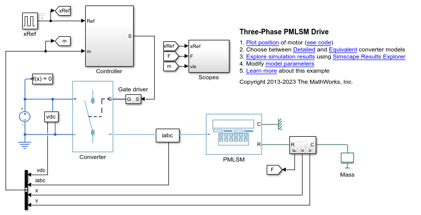
三相 PMLSM 驱动装置
此示例展示了如何控制三相永磁线性同步电机 (PMLSM) 驱动装置中的位置。Control 子系统采用基于 PI 的级联控制结构,包含一个外层位置控制环、一个转速控制环和两个内层电流控制环。通过受控三相转换器为 PMLSM 供电。仿真使用阶跃参考信号。Scopes 子系统包含示波器,可用于查看仿真结果。
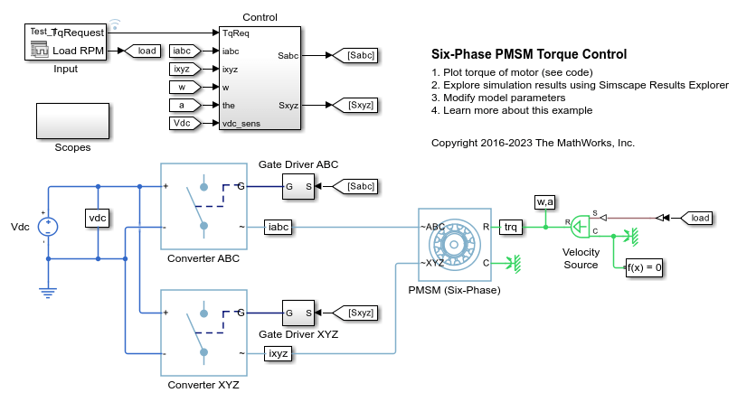
六相 PMSM 转矩控制
此示例展示了如何控制基于六相永磁同步电机 (PMSM) 的电力牵引驱动装置中的转矩。DC 电压源通过两个受控三相转换器为 PMSM 供电。PMSM 根据负载以电机模式和发电模式运行。理想角速度源提供负载。Control 子系统使用开环方法控制转矩,并使用闭环方法控制电流。在每个采样时刻,转矩请求都会转换为相关的 q 轴参考电流。电流控制基于 PI。仿真在电机模式和发电机模式下都使用了多个转矩阶跃。Scopes 子系统包含示波器,可用于查看仿真结果。
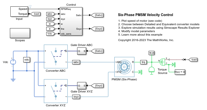
六相 PMSM 速度控制
此示例展示了如何控制基于六相永磁同步电机 (PMSM) 的电力牵引驱动装置中的转子角速度。DC 电压源通过两个受控三相转换器为 PMSM 供电。PMSM 根据负载以电机模式和发电模式运行。理想转矩源提供负载。Scopes 子系统包含示波器,可用于查看仿真结果。Control 子系统包含基于 PI 的级联控制结构,该结构具有一个外层角速度控制环和四个内层电流控制环。在时长一秒的仿真过程中,角速度需求为 0 rpm、500 rpm、2000 rpm,然后是 3000 rpm。

包含热模型的 BLDC 位置控制
此示例展示了如何控制基于 BLDC 的电力驱动装置中的转子角。该 BLDC 包含热模型和经验铁损。理想转矩源提供负载。Control 子系统采用基于 PI 的级联控制结构,包含三个控制环:一个外层位置控制环、一个转速控制环和一个内层电流控制环。BLDC 由受控的三相逆变器供电。逆变器的栅极信号通过霍尔信号获得。仿真使用阶跃参考信号。定子绕组和转子的初始温度设置为 25 摄氏度。环境温度为 27 摄氏度。Scopes 子系统包含示波器,可用于查看仿真结果。
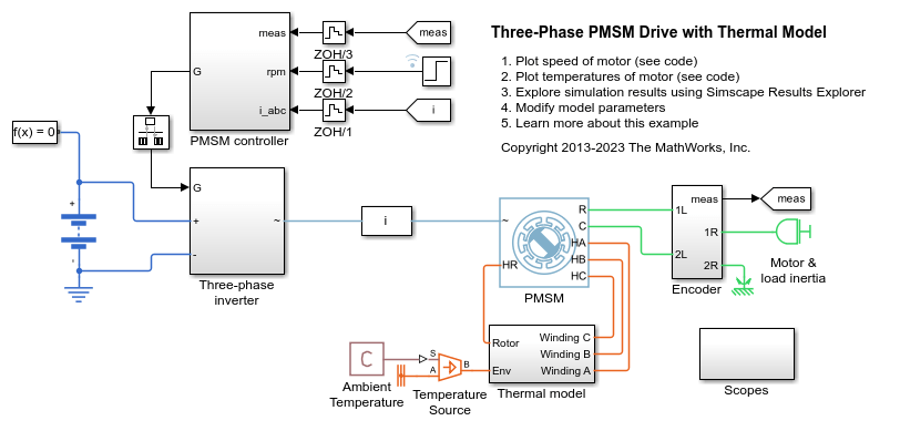
包含热模型的三相 PMSM 驱动
此示例展示了一个永磁同步电机 (PMSM) 以及一个适用于典型混合动力车辆的逆变器。该 PMSM 包含热模型和经验铁损。该逆变器直接连接到车辆电池,但您也可以在两者之间实现一个 DC-DC 转换器阶段。您可以使用此模型设计 PMSM 控制器,通过选择架构和增益来实现期望的性能。定子绕组和转子的初始温度设置为 25 摄氏度。环境温度为 27 摄氏度。Scopes 子系统包含示波器,可用于查看仿真结果。
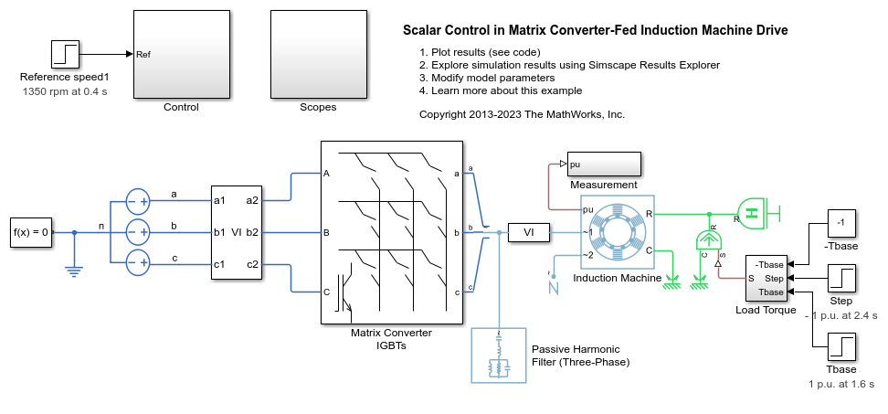
Scalar Control in Matrix Converter-Fed Induction Machine Drive
Control the rotor speed in a matrix converter-fed induction machine drive by using the scalar V/f control method. To generate three-phase voltage with reference frequency, the controller maintains a constant voltage-to frequency ratio though scalar V/f control. A three-phase voltage source with fixed amplitude and frequency feeds the induction machine through a three-phase matrix converter. The matric converter is controlled using third harmonic injection Venturini modulation with unity input displacement factor. The induction machine operates in both motoring and generating modes. The Scopes subsystem contains scopes that allow you to see the simulation results.
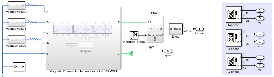
故障 PMSM 建模
此示例展示了如何使用 Simscape™ Electrical™ 对故障永磁同步电机 (PMSM) 进行建模。在对 PMSM 进行建模时,您通常可以将每个绕组表示为一个单一实体,该实体具有关联电感、感应反电动势 (EMF) 以及与相邻绕组的互感耦合。然而,当发生绕组故障时,这种单一实体的假设便不再成立。为了正确捕获由此产生的动态特性,必须在绕组槽级别对电机进行建模。这需要在磁域中进行建模。
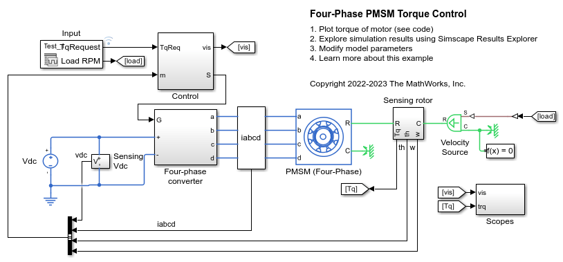
Four-Phase PMSM Torque Control
Control the torque in an electrical-traction drive based on a four-phase permanent magnet synchronous machine (PMSM). A DC voltage source feeds the PMSM through a controlled four-phase converter. The PMSM operates in both motoring and generating modes according to the load. An ideal angular velocity source provides the load. The Control subsystem uses an open-loop approach to control the PMSM torque and a closed-loop approach to control the current. At each sample instant, the torque request is converted to a relevant q-axis current reference. The current control is PI-based. The simulation uses several torque steps in both motor and generator modes. The Scopes subsystem contains scopes that allow you to see the simulation results.

四相 PMSM 速度控制
此示例展示了如何控制基于四相永磁同步电机 (PMSM) 的电力牵引驱动装置中的转子角速度。DC 电压源通过一个受控四相转换器为 PMSM 供电。PMSM 根据负载以电机模式和发电模式运行。理想转矩源提供负载。Scopes 子系统包含示波器,可用于查看仿真结果。Control 子系统包含基于 PI 的级联控制结构,该结构具有一个外层角速度控制环和四个内层电流控制环。在时长一秒的仿真过程中,角速度需求为 0 rpm、500 rpm、2000 rpm,然后是 3000 rpm。

六相开关磁阻电机控制
此示例展示了如何控制基于六相开关磁阻电机 (SRM) 的电力驱动装置中的转子转速。DC 电压源通过受控六臂桥为 SRM 供电。转换器的导通和关断角度保持恒定。
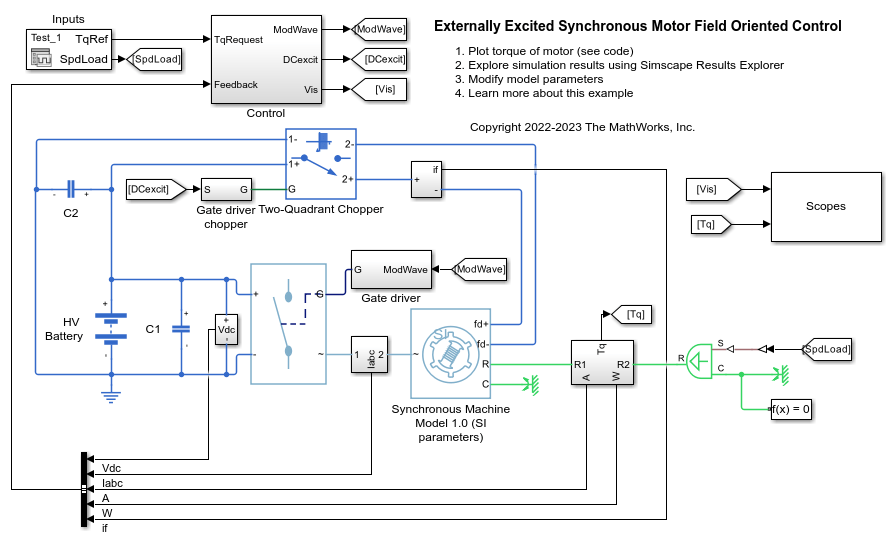
Externally Excited Synchronous Motor Field Oriented Control
Control the torque in an externally excited synchronous motor (SM) drive by using field-oriented control. A high-voltage battery feeds the SM through a controlled three-phase converter for the stator windings and through a controlled two-quadrant chopper for the rotor winding. Both converters are controlled using Averaged Switch and modulation waveforms for fast simulation. The implementation allows you to easily switch to PWM control signals. Current references for the d-axis, q-axis, and excitation are generated offline and implemented using 3-D lookup tables. Use the model to design and evaluate in real-time the SM control algorithm. For controller deployment on an embedded microcontroller, use optimized controllers from the Motor Control Blockset™ libraries. The Scopes subsystem contains scopes that allow you to see the simulation results.
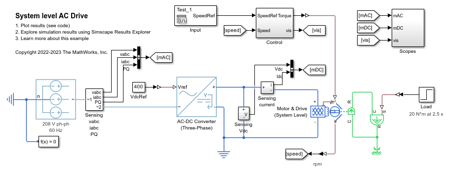
系统级 AC 驱动
此示例展示了如何使用 AC-DC Converter (Three-Phase) 模块和 Motor & Drive (System Level) 模块为电机的系统级 AC 驱动建模。AC-DC 转换器表示提供恒定 DC 链路电压的电网侧转换器。Motor & Drive 模块充当通用 AC 电机及其 DC-AC 转换器。这种建模方法无需功率转换器的开关事件即可提供快速的系统级仿真。
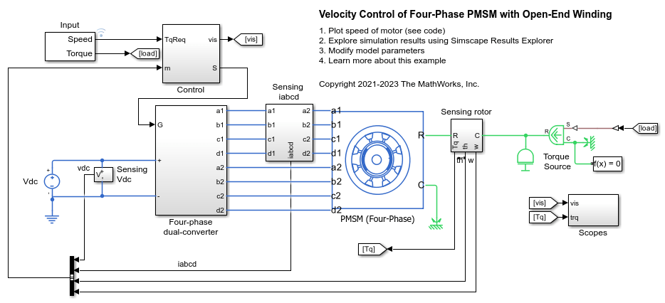
带开放端绕组的四相 PMSM 的速度控制
此示例展示了如何控制电力牵引驱动装置中的转子角转速,该驱动装置使用带开放端绕组的四相永磁同步电机 (PMSM)。要查看 Open-End PMSM (Four-Phase) 模块的源代码,请双击该模块,然后点击“描述”选项卡中的“源代码”超链接。DC 电压源通过两个受控四相转换器为 PMSM 供电。PMSM 根据负载以电机模式和发电模式运行。理想转矩源提供负载。Scopes 子系统包含示波器,可用于查看仿真结果。Control 子系统包含基于 PI 的级联控制结构,该结构具有一个外层角速度控制环和四个内层电流控制环。在时长一秒的仿真过程中,角速度需求为 0 rpm、500 rpm、2000 rpm,然后是 3000 rpm。

Model Start-Up Control Strategy for Wound-Rotor Induction Motor
Design a start-up control strategy with a resistor for a wound-rotor induction model using a Simscape™ Electrical™ FEM-Parameterized Induction Machine (Wound Rotor) block.
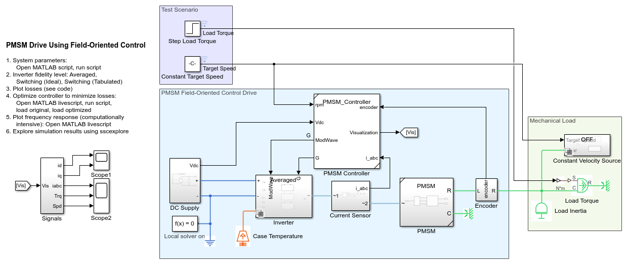
Improve Motor Efficiency with Optimized Control Parameters
Improve the efficiency of a permanent magnet synchronous motor (PMSM) drive using an optimal field-oriented controller (FOC). The FOC has been designed to minimize the motor losses. You can download this model in MATLAB® or access it from MATLAB Central File Exchange and GitHub®.